ALS R Type Mikipulley Viet Nam
Price: Contact
Brand: Mikipulley Viet Nam
Category: Industrial joints
Supplier: Jon&Jul Việt Nam
Origin: Japan
Ứng dụng sản phẩm: accessory, Automation equipment, Electronic, Industry, Mechanical
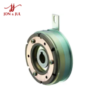
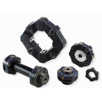
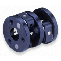
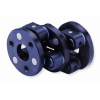
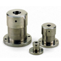
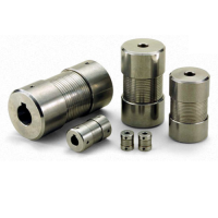
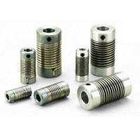
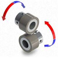
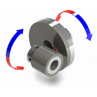
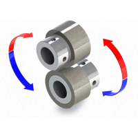
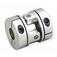
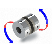
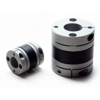
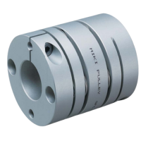
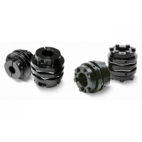
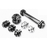
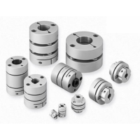
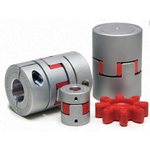
ALS R Type Pulley Industrial coupling Mikipulley Vietnam
Introducing ALS R Type

ALS(R) Type Specifications
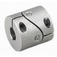
ALS(R) types (key type/screw set)
[Specifications]
| Model | torque | False | Max. rotation speed [min -1] | Static torsional stiffness [N・m/rad] | Radial stiffness [N/mm] | Moment of inertia [kg・m 2] | Weight[kg] | |||
|---|---|---|---|---|---|---|---|---|---|---|
| Nominal [N・m] | Max. [N・m] | Song song [mm] | Angle [°] | Shaft [mm] | ||||||
| ALS-014-R | 2 | 4 | 0,10 | 1 | 0 to +0.6 | 34100 | 21 | 380 | 1,91×10 -7 | 0,007 |
| ALS-020-R | 5 | 10 | 0,10 | 1 | 0 to +0.8 | 23800 | 43 | 400 | 1,08×10 -6 | 0,008 |
| ALS-030-R | 12,5 | 25 | 0,10 | 1 | 0 to +1.0 | 15900 | 136 | 650 | 6,25×10 -6 | 0,047 |
| ALS-040-R | 17 | 34 | 0,10 | 1 | 0 to +1.2 | 11900 | 1550 | 1700 | 3,87×10 -5 | 0,15 |
| ALS-055-R | 60 | 120 | 0,10 | 1 | 0 to +1.4 | 8700 | 2000 | 1350 | 1,66×10 -4 | 0,35 |
| ALS-065-R | 160 | 320 | 0,10 | 1 | 0 to +1.5 | 7400 | 3100 | 1400 | 3,57×10 -4 | 0,51 |
| ALS-080-R | 325 | 650 | 0,10 | 1 | 0 to +1.8 | 6000 | 6000 | 1710 | 1,06×10 -3 | 1,01 |
| ALS-095-R | 450 | 900 | 0,10 | 1 | -0.5 to +2.0 | 5000 | 10000 | 4200 | 2,24×10 -3 | 1,50 |
| ALS-105-R | 525 | 1050 | 0,15 | 1 | -0.9 to +2.0 | 4500 | 12000 | 5000 | 3,72×10 -3 | 2,05 |
*It is not allowed to shift the axis of ALS-014-R to ALS-080-R in the negative direction.
*Max. Rotation speed does not take into account dynamic balance.
*Hardness values given are from measurements performed at 20oC.
*Moment of inertia and mass measured for maximum bore diameter.
[Size]
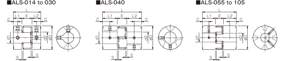
| Model | d1, d2 | D | L | L1, L2 | AND | S | C | ||
|---|---|---|---|---|---|---|---|---|---|
| pilot drill hole | Minimum. | Max. | |||||||
| ALS-014-R | 3 | 3 | 6,5 | 14 | 22 | 7 | 8 | 1 | 3,5 |
| ALS-020-R | 4 | 4 | 9,6 | 20 | 30 | 10 | 10 | 1 | 5 |
| ALS-030-R | 5 | 6 | 14 | 30 | 35 | 11 | 13 | 1,5 | 5,5 |
| ALS-040-R | 5 | 8 | 22 | 40 | 66 | 25 | 16 | 2 | 12,5 |
| ALS-055-R | 5 | 10 | 28 | 55 | 78 | 30 | 18 | 2 | 15 |
| ALS-065-R | 5 | 14 | 38 | 65 | 90 | 35 | 20 | 2,5 | 17,5 |
| ALS-080-R | 10 | 19 | 45 | 80 | 114 | 45 | 24 | 3 | 22,5 |
| ALS-095-R | 8 | 19 | 55 | 95 | 126 | 50 | 26 | 3 | 25 |
| ALS-105-R | 10 | 19 | 60 | 105 | 140 | 56 | 28 | 3,5 | 28 |
*"Pilot range" refers to central processing.
[Standard bore diameter]
| Model | Standard hole diameter d1, d2 [mm] | ||||||||||||||||||||||||||||||||||
|---|---|---|---|---|---|---|---|---|---|---|---|---|---|---|---|---|---|---|---|---|---|---|---|---|---|---|---|---|---|---|---|---|---|---|---|
| 3 | 4 | 5 | 6 | 6:35 | 7 | 8 | 9 | 9,525 | 10 | 11 | 12 | 14 | 15 | 16 | 17 | 18 | 19 | 20 | 22 | 24 | 25 | 28 | 30 | 32 | 35 | 38 | 40 | 42 | 45 | 48 | 50 | 55 | 56 | 60 | |
| ALS-014-R | ● | ● | ● | ● | ● | ||||||||||||||||||||||||||||||
| ALS-020-R | ● | ● | ● | ● | ● | ● | ● | ● | |||||||||||||||||||||||||||
| ALS-030-R | ● | ● | ● | ● | ● | ● | ● | ● | ● | ● | |||||||||||||||||||||||||
| ALS-040-R | ● | ● | ● | ● | ● | ● | ● | ● | ● | ● | ● | ● | ● | ● | |||||||||||||||||||||
| ALS-055-R | ● | ● | ● | ● | ● | ● | ● | ● | ● | ● | ● | ● | ● | ● | |||||||||||||||||||||
| ALS-065-R | ● | ● | ● | ● | ● | ● | ● | ● | ● | ● | ● | ● | ● | ● | ● | ||||||||||||||||||||
| ALS-080-R | ● | ● | ● | ● | ● | ● | ● | ● | ● | ● | ● | ● | ● | ||||||||||||||||||||||
| ALS-095-R | ● | ● | ● | ● | ● | ● | ● | ● | ● | ● | ● | ● | ● | ● | ● | ● | |||||||||||||||||||
| ALS-105-R | ● | ● | ● | ● | ● | ● | ● | ● | ● | ● | ● | ● | ● | ● | ● | ● | ● | ● | |||||||||||||||||
*Bore diameters marked with ● are supported as standard bore diameters.
*ø11 and below without keyway; ø12 and above can be processed according to old JIS standard, new JIS standard and new standard motor.

[Element]
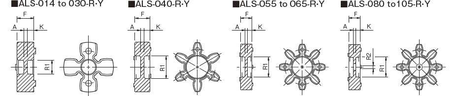
| Model | F | R1 | R2 | K | ONE |
|---|---|---|---|---|---|
| ALS-014-R-EL | 6.2 | 3,5 | -- | 2,5 | 1.2 |
| ALS-020-R-EL | 8.2 | 6.2 | -- | 3,4 | 1.4 |
| ALS-030-R-EL | 10.2 | 8,5 | -- | 4 | 2.2 |
| ALS-040-R-EL | 12 | 18 | -- | 4,5 | 3 |
| ALS-055-R-EL | 14 | 24 | -- | 5,5 | 3 |
| ALS-065-R-EL | 15 | 30 | -- | 5,5 | 4 |
| ALS-080-R-EL | 18 | 37 | 15 | 7 | 4 |
| ALS-095-R-EL | 20 | 43 | 20 | 8 | 4 |
| ALS-105-R-EL | 21 | 50 | 20 | 8,5 | 4 |

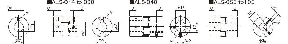
[Standard hole drilling standards]
| Models comply with the old JIS standard (type 2) JIS B 1301 1959 | The models comply with the new JIS standard (H9) JIS B 1301 1996 | Models comply with the new JIS standard (JS9) JIS B 1301 1996 | Model conforms to JIS C 4210 2001 engine standard | ||||||||||||||||
|---|---|---|---|---|---|---|---|---|---|---|---|---|---|---|---|---|---|---|---|
| Nominal hole diameter | Hole diameter [d1・d2] |
Keyway width [W1・W2] |
Keyway height [T1・T2] |
Set screw hole [M] |
Nominal hole diameter | Hole diameter [d1・d2] |
Keyway width [W1・W2] |
Keyway height [T1・T2] |
Set screw hole [M] |
Nominal hole diameter | Hole diameter [d1・d2] |
Keyway width [W1・W2] |
Keyway height [T1・T2] |
Set screw hole [M] |
Nominal hole diameter | Hole diameter [d1・d2] |
Keyway width [W1・W2] |
Keyway height [T1・T2] |
Set screw hole [M] |
| Tolerance H7,H8 |
Tolerance E9 |
- | - | Tolerance H7 |
Tolerance H9 |
- | - | Tolerance H7 |
JS9 Tolerance |
- | - | Tolerance G7,F7 |
Tolerance H9 |
- | - | ||||
| 3 | 3 +0,018 0 | - | - | 1-M3 | - | - | - | - | - | - | - | - | - | - | - | - | - | - | - |
| 4 | 4 +0,018 0 | - | - | 2-M3 | - | - | - | - | - | - | - | - | - | - | - | - | - | - | - |
| 5 | 5 +0,018 0 | - | - | 2-M3 | - | - | - | - | - | - | - | - | - | - | - | - | - | - | - |
| 6 | 6 +0,018 0 | - | - | 2-M4 | - | - | - | - | - | - | - | - | - | - | - | - | - | - | - |
| 6:35 | 6,35 +0,022 0 | - | - | 2-M4 | - | - | - | - | - | - | - | - | - | - | - | - | - | - | - |
| 7 | 7 +0,022 0 | - | - | 2-M4 | - | - | - | - | - | - | - | - | - | - | - | - | - | - | - |
| 8 | 8 +0,022 0 | - | - | 2-M4 | - | - | - | - | - | - | - | - | - | - | - | - | - | - | - |
| 9 | 9 +0,022 0 | - | - | 2-M4 | - | - | - | - | - | - | - | - | - | - | - | - | - | - | - |
| 9,525 | 9,525 +0,022 0 | - | - | 2-M4 | - | - | - | - | - | - | - | - | - | - | - | - | - | - | - |
| 10 | 10 +0,022 0 | - | - | 2-M4 | - | - | - | - | - | - | - | - | - | - | - | - | - | - | - |
| 11 | 11 +0,018 0 | - | - | 2-M4 | - | - | - | - | - | - | - | - | - | - | - | - | - | - | - |
| 12 | 12 +0,018 0 | 4 +0,050 +0,020 | 13,5 +0,3 0 | 2-M4 | 12H | 12 +0,018 0 | 4 +0,030 0 | 13,8 +0,3 0 | 2-M4 | 12J | 12 +0,018 0 | 4 ±0,0150 | 13,8 +0,3 0 | 2-M4 | - | - | - | - | - |
| 14 | 14 +0,018 0 | 5 +0,050 +0,020 | 16,0 +0,3 0 | 2-M4 | 14H | 14 +0,018 0 | 5 +0,030 0 | 16,3 +0,3 0 | 2-M4 | 14Y | 14 +0,018 0 | 5 ±0,0150 | 16,3 +0,3 0 | 2-M4 | 14N | 14 +0,024 +0,006 | 5 +0,030 0 | 16,3 +0,3 0 | 2-M4 |
| 15 | 15 +0,018 0 | 5 +0,050 +0,020 | 17,0 +0,3 0 | 2-M4 | 15H | 15 +0,018 0 | 5 +0,030 0 | 17,3 +0,3 0 | 2-M4 | 15J | 15 +0,018 0 | 5 ±0,0150 | 17,3 +0,3 0 | 2-M4 | - | - | - | - | - |
| 16 | 16 +0,018 0 | 5 +0,050 +0,020 | 18,0 +0,3 0 | 2-M4 | 16H | 16 +0,018 0 | 5 +0,030 0 | 18,3 +0,3 0 | 2-M4 | 16J | 16 +0,018 0 | 5 ±0,0150 | 18,3 +0,3 0 | 2-M4 | - | - | - | - | - |
| 17 | 17 +0,018 0 | 5 +0,050 +0,020 | 19,0 +0,3 0 | 2-M4 | 17H | 17 +0,018 0 | 5 +0,030 0 | 19,3 +0,3 0 | 2-M4 | 17J | 17 +0,018 0 | 5 ±0,0150 | 19,3 +0,3 0 | 2-M4 | - | - | - | - | - |
| 18 | 18 +0,018 0 | 5 +0,050 +0,020 | 20,0 +0,3 0 | 2-M4 | 18H | 18 +0,018 0 | 6 +0,030 0 | 20,8 +0,3 0 | 2-M5 | 18J | 18 +0,018 0 | 6 ±0,0150 | 20,8 +0,3 0 | 2-M5 | - | - | - | - | - |
| 19 | 19 +0,021 0 | 5 +0,050 +0,020 | 21,0 +0,3 0 | 2-M4 | 19H | 19 +0,021 0 | 6 +0,030 0 | 21,8 +0,3 0 | 2-M5 | 19J | 19 +0,021 0 | 6 ±0,0150 | 21,8 +0,3 0 | 2-M5 | 19N | 19 +0,028 +0,007 | 6 +0,030 0 | 21,8 +0,3 0 | 2-M5 |
| 20 | 20 +0,021 0 | 5 +0,050 +0,020 | 22,0 +0,3 0 | 2-M4 | 20H | 20 +0,021 0 | 6 +0,030 0 | 22,8 +0,3 0 | 2-M5 | 20J | 20 +0,021 0 | 6 ±0,0150 | 22,8 +0,3 0 | 2-M5 | - | - | - | - | - |
| 22 | 22 +0,021 0 | 7 +0,061 +0,025 | 25,0 +0,3 0 | 2-M6 | 10 p.m | 22 +0,021 0 | 6 +0,030 0 | 24,8 +0,3 0 | 2-M5 | 22J | 22 +0,021 0 | 6 ±0,0150 | 24,8 +0,3 0 | 2-M5 | - | - | - | - | - |
| 24 | 24 +0,021 0 | 7 +0,061 +0,025 | 27,0 +0,3 0 | 2-M6 | 24H | 24 +0,021 0 | 8 +0,036 0 | 27,3 +0,3 0 | 2-M6 | 24J | 24 +0,021 0 | 8 ±0,0180 | 27,3 +0,3 0 | 2-M6 | 24N | 24 +0,028 +0,007 | 8 +0,036 0 | 27,3 +0,3 0 | 2-M6 |
| 25 | 25 +0,021 0 | 7 +0,061 +0,025 | 28,0 +0,3 0 | 2-M6 | 25H | 25 +0,021 0 | 8 +0,036 0 | 28,3 +0,3 0 | 2-M6 | 25J | 25 +0,021 0 | 8 ±0,0180 | 28,3 +0,3 0 | 2-M6 | - | - | - | - | - |
| 28 | 28 +0,021 0 | 7 +0,061 +0,025 | 31,0 +0,3 0 | 2-M6 | 28 hours | 28 +0,021 0 | 8 +0,036 0 | 31,3 +0,3 0 | 2-M6 | 28J | 28 +0,021 0 | 8 ±0,0180 | 31,3 +0,3 0 | 2-M6 | 28N | 28 +0,028 +0,007 | 8 +0,036 0 | 31,3 +0,3 0 | 2-M6 |
| 30 | 30 +0,021 0 | 7 +0,061 +0,025 | 33,0 +0,3 0 | 2-M6 | 30 hours | 30 +0,021 0 | 8 +0,036 0 | 33,3 +0,3 0 | 2-M6 | 30J | 30 +0,021 0 | 8 ±0,0180 | 33,3 +0,3 0 | 2-M6 | - | - | - | - | - |
| 32 | 32 +0,025 0 | 10 +0,061 +0,025 | 35,5 +0,3 0 | 2-M8 | 32H | 32 +0,025 0 | 10 +0,036 0 | 35,3 +0,3 0 | 2-M8 | 32J | 32 +0,025 0 | 10 ±0,0180 | 35,3 +0,3 0 | 2-M8 | - | - | - | - | - |
| 35 | 35 +0,025 0 | 10 +0,061 +0,025 | 38,5 +0,3 0 | 2-M8 | 35H | 35 +0,025 0 | 10 +0,036 0 | 38,3 +0,3 0 | 2-M8 | 35J | 35 +0,025 0 | 10 ±0,0180 | 38,3 +0,3 0 | 2-M8 | - | - | - | - | - |
| 38 | 38 +0,025 0 | 10 +0,061 +0,025 | 41,5 +0,3 0 | 2-M8 | 38H | 38 +0,025 0 | 10 +0,036 0 | 41,3 +0,3 0 | 2-M8 | 38J | 38 +0,025 0 | 10 ±0,0180 | 41,3 +0,3 0 | 2-M8 | 38N | 38 +0,050 +0,025 | 10 +0,036 0 | 41,3 +0,3 0 | 2-M8 |
| 40 | 40 +0,025 0 | 10 +0,061 +0,025 | 43,5 +0,3 0 | 2-M8 | 40H | 40 +0,025 0 | 12 +0,043 0 | 43,3 +0,3 0 | 2-M8 | 40J | 40 +0,025 0 | 12 ±0,0215 | 43,3 +0,3 0 | 2-M8 | - | - | - | - | - |
| 42 | 42 +0,025 0 | 12 +0,075 +0,032 | 45,5 +0,3 0 | 2-M8 | 42H | 42 +0,025 0 | 12 +0,043 0 | 45,3 +0,3 0 | 2-M8 | 42J | 42 +0,025 0 | 12 ±0,0215 | 45,3 +0,3 0 | 2-M8 | 42N | 42 +0,050 +0,025 | 12 +0,043 0 | 45,3 +0,3 0 | 2-M8 |
| 45 | 45 +0,025 0 | 12 +0,075 +0,032 | 48,5 +0,3 0 | 2-M8 | 45H | 45 +0,025 0 | 14 +0,043 0 | 48,8 +0,3 0 | 2-M10 | 45J | 45 +0,025 0 | 14 ±0,0215 | 48,8 +0,3 0 | 2-M10 | - | - | - | - | - |
| 48 | 48 +0,025 0 | 12 +0,075 +0,032 | 51,5 +0,3 0 | 2-M8 | 48H | 48 +0,025 0 | 14 +0,043 0 | 51,8 +0,3 0 | 2-M10 | 48J | 48 +0,025 0 | 14 ±0,0215 | 51,8 +0,3 0 | 2-M10 | 48N | 48 +0,050 +0,025 | 14 +0,043 0 | 51,8 +0,3 0 | 2-M10 |
| 50 | 50 +0,025 0 | 12 +0,075 +0,032 | 53,5 +0,3 0 | 2-M8 | 50H | 50 +0,025 0 | 14 +0,043 0 | 53,8 +0,3 0 | 2-M10 | 50J | 50 +0,025 0 | 14 ±0,0215 | 53,8 +0,3 0 | 2-M10 | - | - | - | - | - |
| 55 | 55 +0,030 0 | 15 +0,075 +0,032 | 60,0 +0,3 0 | 2-M10 | 55H | 55 +0,030 0 | 16 +0,043 0 | 59,3 +0,3 0 | 2-M10 | 55J | 55 +0,030 0 | 16 ±0,0215 | 59,3 +0,3 0 | 2-M10 | 55N | 55 +0,060 +0,030 | 16 +0,043 0 | 59,3 +0,3 0 | 2-M10 |
| 56 | 56 +0,030 0 | 15 +0,075 +0,032 | 61,0 +0,3 0 | 2-M10 | 56H | 56 +0,030 0 | 16 +0,043 0 | 60,3 +0,3 0 | 2-M10 | 56J | 56 +0,030 0 | 16 ±0,0215 | 60,3 +0,3 0 | 2-M10 | - | - | - | - | - |
| 60 | 60 +0,030 0 | 15 +0,075 +0,032 | 65,0 +0,3 0 | 2-M10 | 60H | 60 +0,030 0 | 18 +0,043 0 | 64,4 +0,3 0 | 2-M10 | 60J | 60 +0,030 0 | 18 ±0,0215 | 64,4 +0,3 0 | 2-M10 | 60N | 60 +0,060 +0,030 | 18 +0,043 0 | 64,4 +0,3 0 | 2-M10 |
*All standards starting from ø11 are the same as those in the old JIS standards column.
*For ALS-014, the set screw size is M3.
*The positions of the set screw and keyway are not on the same plane.
*Screw set is included in the product.
*Positioning accuracy for keyway milling is determined by eye.
*Contact Miki Pulley when keyway positioning accuracy is required for a specific flange shaft.
*Refer to the technical documentation at the end of this volume for standard dimensions for bore drilling in addition to those given here.
[Set screw position]
| Model | Distance C from edge[mm] |
|---|---|
| ALS-014 | 3,5 |
| ALS-020 | 5 |
| ALS-030 | 5,5 |
| ALS-040 | 12,5 |
| ALS-055 | 15 |
| ALS-065 | 17,5 |
| ALS-080 | 22,5 |
| ALS-095 | 25 |
| ALS-105 | 28 |
Type ALS(R) (clip type)
[Specifications]
| Model | False | Max. rotation speed [min -1] | Static torsional stiffness [N・m/rad] | Radial stiffness [N/mm] | Moment of inertia [kg・m 2] | Weight[kg] | ||
|---|---|---|---|---|---|---|---|---|
| Song song [mm] | Angle [°] | Shaft [mm] | ||||||
| ALS-014-R | 0,1 | 1 | 0 to +0.6 | 10000 | 21 | 380 | 1,98×10 -7 | 0,007 |
| ALS-020-R | 0,1 | 1 | 0 to +0.8 | 10000 | 43 | 400 | 1,09×10 -6 | 0,019 |
| ALS-030-R | 0,1 | 1 | 0 to +1.0 | 10000 | 136 | 650 | 6,19×10 -6 | 0,045 |
| ALS-040-R | 0,1 | 1 | 0 to +1.2 | 10000 | 1550 | 1700 | 4,01×10 -5 | 0,16 |
| ALS-055-R | 0,1 | 1 | 0 to +1.4 | 7000 | 2000 | 1350 | 1,63×10 -4 | 0,34 |
| ALS-065-R | 0,1 | 1 | 0 to +1.5 | 5900 | 3100 | 1400 | 3,69×10 -4 | 0,54 |
| ALS-080-R | 0,1 | 1 | 0 to +1.8 | 4800 | 6000 | 1710 | 1,04×10 -3 | 1,00 |
* Axis displacement in the negative direction is not allowed.
*Max. Rotation speed does not take into account dynamic balance.
*Hardness values given are from measurements performed at 20oC.
*Moment of inertia and mass measured for maximum bore diameter.
[Size]
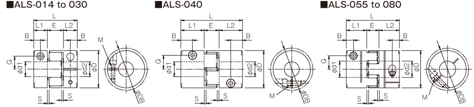
| Model | d1, d2 | D | database | L | L1, L2 | AND | S | B | G | M | Tightening torque [N・m] | |
|---|---|---|---|---|---|---|---|---|---|---|---|---|
| Minimum. | Max. | |||||||||||
| ALS-014-R | 3 | 6 | 14 | 16.1 | 22 | 7 | 8 | 1 | 3,5 | 4,8 | 1-M2 | 0,4 |
| ALS-020-R | 4 | 8 | 20 | 20 | 30 | 10 | 10 | 1 | 5 | 6,5 | 1-M2.5 | 1 |
| ALS-030-R | 6 | 14 | 30 | 30 | 35 | 11 | 13 | 1,5 | 5,5 | 10,5 | 1-M3 | 1,5 |
| ALS-040-R | 8 | 20 | 40 | 43,2 | 66 | 25 | 16 | 2 | 12,5 | 15 | 1-M5 | 7 |
| ALS-055-R | 10 | 28 | 55 | 55 | 78 | 30 | 18 | 2 | 10,5 | 20 | 1-M6 | 14 |
| ALS-065-R | 14 | 35 | 65 | 69,8 | 90 | 35 | 20 | 2,5 | 11,5 | 24,5 | 1-M8 | 30 |
| ALS-080-R | 19 | 45 | 80 | 80 | 114 | 45 | 24 | 3 | 11,5 | 30 | 1-M8 | 30 |
*øDB values are measured assuming that the head of the clamping bolt is larger than the outside diameter of the hub.
*The nominal diameter of the clamping bolt M is equal to the quantity minus the nominal diameter of the screw thread, where the quantity is for the hub on one side.
Standard bore diameter and allowable drive torque
| Model | Standard hole diameter d1, d2 [mm] and rated transmission torque [N・m] | ||||||||||||||||||||||||||||
|---|---|---|---|---|---|---|---|---|---|---|---|---|---|---|---|---|---|---|---|---|---|---|---|---|---|---|---|---|---|
| 3 | 4 | 5 | 6 | 6:35 | 7 | 8 | 9 | 9,525 | 10 | 11 | 12 | 14 | 15 | 16 | 18 | 19 | 20 | 22 | 24 | 25 | 28 | 30 | 32 | 35 | 38 | 40 | 42 | 45 | |
| ALS-014-R | 0,31 | 0,42 | 0,54 | 0,65 | |||||||||||||||||||||||||
| ALS-020-R | 1.2 | 1.6 | 2.1 | 2.2 | 2.6 | 3 | |||||||||||||||||||||||
| ALS-030-R | 2 | 2.2 | 2.7 | 3,4 | 4 | 4.4 | 4,7 | 5,4 | 6 | 7.4 | |||||||||||||||||||
| ALS-040-R | 8 | 12 | 14 | 16 | 19 | 23 | 31 | 34 | 34 | 34 | 34 | 34 | |||||||||||||||||
| ALS-055-R | 21 | 25 | 28 | 35 | 38 | 41 | 48 | 51 | 54 | 61 | 67 | 71 | 80 | ||||||||||||||||
| ALS-065-R | 40 | 44 | 47 | 54 | 58 | 61 | 68 | 75 | 79 | 89 | 96 | 103 | 114 | ||||||||||||||||
| ALS-080-R | 53 | 59 | 72 | 84 | 90 | 108 | 121 | 133 | 151 | 170 | 182 | 194 | 212 | ||||||||||||||||
*Hole diameters with numeric fields are supported as standard hole diameters.
*The field bore diameter contains numbers limited in the rated transmission torque by the holding capacity of the shaft connection. The numbers represent the rated transmission torque value [N·m].
*Recommended processing tolerance for coupled mounting shafts is type h7. However, for bore diameter ø35, the shaft tolerance is -0.025 to +0.010
*Bore diameters between the minimum and maximum shown in the dimension table are compatible, but bore diameters other than those shown in the table above require a different arrangement. Contact Miki Pulley for more details.
[Element]
| Model | F | R1 | R2 | K | ONE |
|---|---|---|---|---|---|
| ALS-014-R-EL | 6.2 | 3,5 | -- | 2,5 | 1.2 |
| ALS-020-R-EL | 8.2 | 6.2 | -- | 3,4 | 1.4 |
| ALS-030-R-EL | 10.2 | 8,5 | -- | 4 | 2.2 |
| ALS-040-R-EL | 12 | 18 | -- | 4,5 | 3 |
| ALS-055-R-EL | 14 | 24 | -- | 5,5 | 3 |
| ALS-065-R-EL | 15 | 30 | -- | 5,5 | 4 |
| ALS-080-R-EL | 18 | 37 | 15 | 7 | 4 |
| ALS-095-R-EL | 20 | 43 | 20 | 8 | 4 |
| ALS-105-R-EL | 21 | 50 | 20 | 8,5 | 4 |
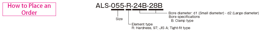
See more technical documents here
See more technical products here
Link FaceBook Jon&Jul VietNam