SFS Models Mikipulley Việt Nam
Price: Contact
Brand: Mikipulley Viet Nam
Category: Industrial joints
Supplier: Jon&Jul Việt Nam
Origin: Japan
Ứng dụng sản phẩm: accessory, Automation equipment, Electronic, Industry, Mechanical
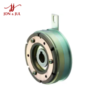
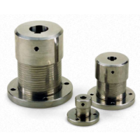
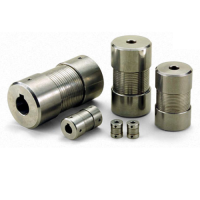
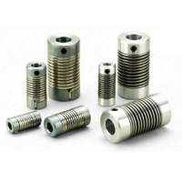
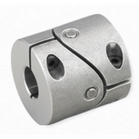
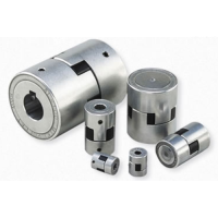
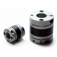
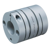
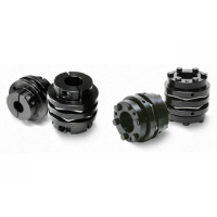
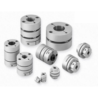
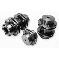
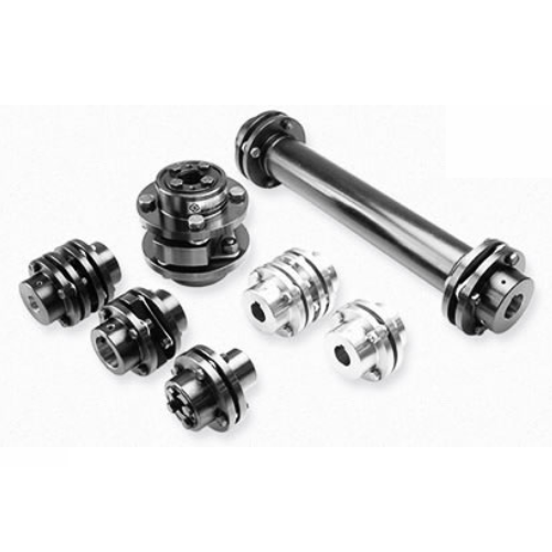
SFS Models Pulley Industrial Couplings Mikipulley Vietnam
Introducing SFS Models

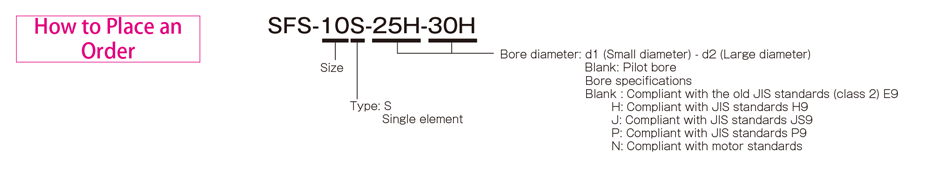
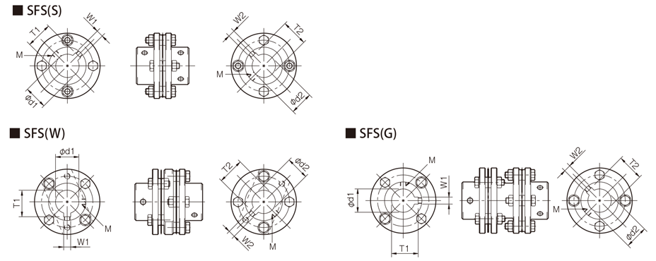
Types of SFS-□S
[Specifications]
| Model | Rated torque[N・m] | False | Max. rotation speed[min -1] | Torsional stiffness[N・m/rad] | Axial stiffness[N/mm] | Moment of inertia[kg・m 2] | Weight[kg] | |
|---|---|---|---|---|---|---|---|---|
| Angle[°] | Shaft[mm] | |||||||
| SFS-05S | 20 | 1 | ±0,6 | 25000 | 16000 | 43 | 0,11×10 -3 | 0,30 |
| SFS-06S | 40 | 1 | ±0,8 | 20000 | 29000 | 45 | 0,30×10 -3 | 0,50 |
| SFS-08S | 80 | 1 | ±1,0 | 17000 | 83000 | 60 | 0,87×10 -3 | 1,00 |
| SFS-09S | 180 | 1 | ±1,2 | 15000 | 170000 | 122 | 1,60×10 -3 | 1,40 |
| SFS-10S | 250 | 1 | ±1,4 | 13000 | 250000 | 160 | 2,60×10 -3 | 2.10 |
| SFS-12S | 450 | 1 | ±1,6 | 11000 | 430000 | 197 | 6,50×10 -3 | 3,40 |
| SFS-14S | 800 | 1 | ±1,8 | 9500 | 780000 | 313 | 9,90×10 -3 | 4,90 |
*Max. Rotation speed does not take into account dynamic balance.
*Moment of inertia and mass measured for maximum bore diameter.
[Size]

| Model | d1・d2 | D | N | L | LF | S | F | K | M | ||
|---|---|---|---|---|---|---|---|---|---|---|---|
| pilot drill hole | Minimum. | Max. | |||||||||
| SFS-05S | 7 | 8 | 20 | 56 | 32 | 45 | 20 | 5 | 11 | 24 | 4-M5×22 |
| SFS-06S | 7 | 8 | 25 | 68 | 40 | 56 | 25 | 6 | 10 | 30 | 4-M6×25 |
| SFS-08S | 10 | 11 | 35 | 82 | 54 | 66 | 30 | 6 | 11 | 38 | 4-M6×29 |
| SFS-09S | 10 | 11 | 38 | 94 | 58 | 68 | 30 | 8 | 21 | 42 | 4-M8×36 |
| SFS-10S | 15 | 16 | 42 | 104 | 68 | 80 | 35 | 10 | 16 | 48 | 4-M8×36 |
| SFS-12S | 18 | 19 | 50 | 126 | 78 | 91 | 40 | 11 | 23 | 54 | 4-M10×45 |
| SFS-14S | 20 | 22 | 60 | 144 | 88 | 102 | 45 | 12 | 31 | 61 | 4-M12×54 |
* Pilot holes must be drilled into the part.
* The nominal diameter of a bored bolt M is equal to the quantity minus the nominal diameter of the screw thread multiplied by the nominal length.
[Standard bore diameter]
| Model | Standard hole diameter d1・d2 [mm] | |||||||||||||||||||||||||||
|---|---|---|---|---|---|---|---|---|---|---|---|---|---|---|---|---|---|---|---|---|---|---|---|---|---|---|---|---|
| 8 | 9 | 10 | 11 | 12 | 14 | 15 | 16 | 17 | 18 | 19 | 20 | 22 | 24 | 25 | 28 | 30 | 32 | 35 | 38 | 40 | 42 | 45 | 48 | 50 | 55 | 56 | 60 | |
| SFS-05S | ● | ● | ● | ● | ● | ● | ● | ● | ● | ● | ● | ● | ||||||||||||||||
| SFS-06S | ● | ● | ● | ● | ● | ● | ● | ● | ● | ● | ● | ● | ● | ● | ● | |||||||||||||
| SFS-08S | ● | ● | ● | ● | ● | ● | ● | ● | ● | ● | ● | ● | ● | ● | ● | ● | ||||||||||||
| SFS-09S | ● | ● | ● | ● | ● | ● | ● | ● | ● | ● | ● | ● | ● | ● | ● | ● | ● | |||||||||||
| SFS-10S | ● | ● | ● | ● | ● | ● | ● | ● | ● | ● | ● | ● | ● | ● | ● | |||||||||||||
| SFS-12S | ● | ● | ● | ● | ● | ● | ● | ● | ● | ● | ● | ● | ● | ● | ● | |||||||||||||
| SFS-14S | ● | ● | ● | ● | ● | ● | ● | ● | ● | ● | ● | ● | ● | ● | ● | ● | ||||||||||||
* Hole diameters marked with ● are supported as standard hole diameters. See standard hole drilling standards for information.
[Standard hole drilling standards]
| Models comply with the old JIS standard (type 2) JIS B 1301 1959 | The models comply with the new JIS standard (H9) JIS B 1301 1996 | Models comply with the new JIS standard (JS9) JIS B 1301 1996 | ||||||||||||
|---|---|---|---|---|---|---|---|---|---|---|---|---|---|---|
| Nominal hole diameter | Bore diameter(d1・d2) | Keyway height(W1・W2) | Keyway height(T1・T2) | Set the screw hole(M | Nominal hole diameter | Bore diameter(d1・d2) | Keyway height(W1・W2) | Keyway height(T1・T2) | Set the screw hole(M | Nominal hole diameter | Bore diameter(d1・d2) | Keyway height(W1・W2) | Keyway height(T1・T2) | Set the screw hole(M |
| ToleranceH7,H8 | ToleranceE9 | - | - | ToleranceH7,H8 | ToleranceH9 | - | - | ToleranceH7,H8 | ToleranceJS9 | - | - | |||
| 8 | 8 +0,022 0 | - | - | 2-M4 | 8 O'CLOCK | 8 +0,022 0 | 3 +0,025 0 | 9,4 +0,3 0 | 2-M4 | 8J | 8 +0,022 0 | 3 ±0,0125 | 9,4 +0,3 0 | 2-M4 |
| 9 | 9 +0,022 0 | - | - | 2-M4 | 9H | 9 +0,022 0 | 3 +0,025 0 | 10,4 +0,3 0 | 2-M4 | 9J | 9 +0,022 0 | 3 ±0,0125 | 10,4 +0,3 0 | 2-M4 |
| 10 | 10 +0,022 0 | - | - | 2-M4 | 10H | 10 +0,022 0 | 3 +0,025 0 | 11,4 +0,3 0 | 2-M4 | 10J | 10 +0,022 0 | 3 ±0,0125 | 11,4 +0,3 0 | 2-M4 |
| 11 | 11 +0,018 0 | - | - | 2-M4 | 11H | 11 +0,018 0 | 4 +0,030 0 | 12,8 +0,3 0 | 2-M4 | 11J | 11 +0,018 0 | 4 ±0,0150 | 12,8 +0,3 0 | 2-M4 |
| 12 | 12 +0,018 0 | 4 +0,050 +0,020 | 13,5 +0,3 0 | 2-M4 | 12H | 12 +0,018 0 | 4 +0,030 0 | 13,8 +0,3 0 | 2-M4 | 12J | 12 +0,018 0 | 4 ±0,0150 | 13,8 +0,3 0 | 2-M4 |
| 14 | 14 +0,018 0 | 5 +0,050 +0,020 | 16 +0,3 0 | 2-M4 | 14H | 14 +0,018 0 | 5 +0,030 0 | 16,3 +0,3 0 | 2-M4 | 14Y | 14 +0,018 0 | 5 ±0,0150 | 16,3 +0,3 0 | 2-M4 |
| 15 | 15 +0,018 0 | 5 +0,050 +0,020 | 17 +0,3 0 | 2-M4 | 15H | 15 +0,018 0 | 5 +0,030 0 | 17,3 +0,3 0 | 2-M4 | 15J | 15 +0,018 0 | 5 ±0,0150 | 17,3 +0,3 0 | 2-M4 |
| 16 | 16 +0,018 0 | 5 +0,050 +0,020 | 18 +0,3 0 | 2-M4 | 16H | 16 +0,018 0 | 5 +0,030 0 | 18,3 +0,3 0 | 2-M4 | 16J | 16 +0,018 0 | 5 ±0,0150 | 18,3 +0,3 0 | 2-M4 |
| 17 | 17 +0,018 0 | 5 +0,050 +0,020 | 19 +0,3 0 | 2-M4 | 17H | 17 +0,018 0 | 5 +0,030 0 | 19,3 +0,3 0 | 2-M4 | 17J | 17 +0,018 0 | 5 ±0,0150 | 19,3 +0,3 0 | 2-M4 |
| 18 | 18 +0,018 0 | 5 +0,050 +0,020 | 20 +0,3 0 | 2-M4 | 18H | 18 +0,018 0 | 6 +0,030 0 | 20,8 +0,3 0 | 2-M5 | 18J | 18 +0,018 0 | 6 ±0,0150 | 20,8 +0,3 0 | 2-M5 |
| 19 | 19 +0,021 0 | 5 +0,050 +0,020 | 21 +0,3 0 | 2-M4 | 19H | 19 +0,021 0 | 6 +0,030 0 | 21,8 +0,3 0 | 2-M5 | 19J | 19 +0,021 0 | 6 ±0,0150 | 21,8 +0,3 0 | 2-M5 |
| 20 | 20 +0,021 0 | 5 +0,050 +0,020 | 22 +0,3 0 | 2-M4 | 20H | 20 +0,021 0 | 6 +0,030 0 | 22,8 +0,3 0 | 2-M5 | 20J | 20 +0,021 0 | 6 ±0,0150 | 22,8 +0,3 0 | 2-M5 |
| 22 | 22 +0,021 0 | 7 +0,061 +0,025 | 25 +0,3 0 | 2-M6 | 10 p.m | 22 +0,021 0 | 6 +0,030 0 | 24,8 +0,3 0 | 2-M5 | 22J | 22 +0,021 0 | 6 ±0,0150 | 24,8 +0,3 0 | 2-M5 |
| 24 | 24 +0,021 0 | 7 +0,061 +0,025 | 27 +0,3 0 | 2-M6 | 24H | 24 +0,021 0 | 8 +0,036 0 | 27,3 +0,3 0 | 2-M6 | 24J | 24 +0,021 0 | 8 ±0,0180 | 27,3 +0,3 0 | 2-M6 |
| 25 | 25 +0,021 0 | 7 +0,061 +0,025 | 28 +0,3 0 | 2-M6 | 25H | 25 +0,021 0 | 8 +0,036 0 | 28,3 +0,3 0 | 2-M6 | 25J | 25 +0,021 0 | 8 ±0,0180 | 28,3 +0,3 0 | 2-M6 |
| 28 | 28 +0,021 0 | 7 +0,061 +0,025 | 31 +0,3 0 | 2-M6 | 28 hours | 28 +0,021 0 | 8 +0,036 0 | 31,3 +0,3 0 | 2-M6 | 28J | 28 +0,021 0 | 8 ±0,0180 | 31,3 +0,3 0 | 2-M6 |
| 30 | 30 +0,021 0 | 7 +0,061 +0,025 | 33 +0,3 0 | 2-M6 | 30 hours | 30 +0,021 0 | 8 +0,036 0 | 33,3 +0,3 0 | 2-M6 | 30J | 30 +0,021 0 | 8 ±0,0180 | 33,3 +0,3 0 | 2-M6 |
| 32 | 32 +0,025 0 | 10 +0,061 +0,025 | 35,5 +0,3 0 | 2-M8 | 32H | 32 +0,025 0 | 10 +0,036 0 | 35,3 +0,3 0 | 2-M8 | 32J | 32 +0,025 0 | 10 ±0,0180 | 35,3 +0,3 0 | 2-M8 |
| 35 | 35 +0,025 0 | 10 +0,061 +0,025 | 38,5 +0,3 0 | 2-M8 | 35H | 35 +0,025 0 | 10 +0,036 0 | 38,3 +0,3 0 | 2-M8 | 35J | 35 +0,025 0 | 10 ±0,0180 | 38,3 +0,3 0 | 2-M8 |
| 38 | 38 +0,025 0 | 10 +0,061 +0,025 | 41,5 +0,3 0 | 2-M8 | 38H | 38 +0,025 0 | 10 +0,036 0 | 41,3 +0,3 0 | 2-M8 | 38J | 38 +0,025 0 | 10 ±0,0180 | 41,3 +0,3 0 | 2-M8 |
| 40 | 40 +0,025 0 | 10 +0,061 +0,025 | 43,5 +0,3 0 | 2-M8 | 40H | 40 +0,025 0 | 12 +0,043 0 | 43,3 +0,3 0 | 2-M8 | 40J | 40 +0,025 0 | 12 ±0,0215 | 43,3 +0,3 0 | 2-M8 |
| 42 | 42 +0,025 0 | 12 +0,075 +0,032 | 45,5 +0,3 0 | 2-M8 | 42H | 42 +0,025 0 | 12 +0,043 0 | 45,3 +0,3 0 | 2-M8 | 42J | 42 +0,025 0 | 12 ±0,0215 | 45,3 +0,3 0 | 2-M8 |
| 45 | 45 +0,025 0 | 12 +0,075 +0,032 | 48,5 +0,3 0 | 2-M8 | 45H | 45 +0,025 0 | 14 +0,043 0 | 48,8 +0,3 0 | 2-M10 | 45J | 45 +0,025 0 | 14 ±0,0215 | 48,8 +0,3 0 | 2-M10 |
| 48 | 48 +0,025 0 | 12 +0,075 +0,032 | 51,5 +0,3 0 | 2-M8 | 48H | 48 +0,025 0 | 14 +0,043 0 | 51,8 +0,3 0 | 2-M10 | 48J | 48 +0,025 0 | 14 ±0,0215 | 51,8 +0,3 0 | 2-M10 |
| 50 | 50 +0,025 0 | 12 +0,075 +0,032 | 53,5 +0,3 0 | 2-M8 | 50H | 50 +0,025 0 | 14 +0,043 0 | 53,8 +0,3 0 | 2-M10 | 50J | 50 +0,025 0 | 14 ±0,0215 | 53,8 +0,3 0 | 2-M10 |
| 55 | 55 +0,030 0 | 15 +0,075 +0,032 | 60 +0,3 0 | 2-M10 | 55H | 55 +0,030 0 | 16 +0,043 0 | 59,3 +0,3 0 | 2-M10 | 55J | 55 +0,030 0 | 16 ±0,0215 | 59,3 +0,3 0 | 2-M10 |
| 56 | 56 +0,030 0 | 15 +0,075 +0,032 | 61 +0,3 0 | 2-M10 | 56H | 56 +0,030 0 | 16 +0,043 0 | 60,3 +0,3 0 | 2-M10 | 56J | 56 +0,030 0 | 16 ±0,0215 | 60,3 +0,3 0 | 2-M10 |
| 60 | 60 +0,030 0 | 15 +0,075 +0,032 | 65 +0,3 0 | 2-M10 | 60H | 60 +0,030 0 | 18 +0,043 0 | 64,4 +0,3 0 | 2-M10 | 60J | 60 +0,030 0 | 18 ±0,0215 | 64,4 +0,3 0 | 2-M10 |
| The models comply with the new JIS standard (P9) JIS B 1301 1996 | Model conforms to JIS C 4210 2001 engine standard | ||||||||
|---|---|---|---|---|---|---|---|---|---|
| Nominal hole diameter | Bore diameter(d1・d2) | Keyway width(W1・W2) | Keyway height(T1・T2) | Set the screw hole(M | Nominal hole diameter | Bore diameter(d1・d2) | Keyway width(W1・W2) | Keyway height(T1・T2) | Set the screw hole(M |
| ToleranceH7,H8 | ToleranceP9 | + 0,30 0 | - | - | ToleranceG7,F7 | ToleranceH9 | - | ||
| 8P | 8 +0,022 | 3 -0,006 -0,031 | 9,4 +0,3 0 | 2-M4 | - | - | - | - | - |
| 9P | 9 +0,022 | 3 -0,006 -0,031 | 10,4 +0,3 0 | 2-M4 | - | - | - | - | - |
| 10P | 10 +0,022 | 3 -0,006 -0,031 | 11,4 +0,3 0 | 2-M4 | - | - | - | - | - |
| 11P | 11 +0,018 | 4 -0,042 -0,012 | 12,8 +0,3 0 | 2-M4 | - | - | - | - | - |
| 12P | 12 +0,018 | 4 -0,042 -0,012 | 13,8 +0,3 0 | 2-M4 | - | - | - | - | - |
| 14P | 14 +0,018 | 5 -0,042 -0,012 | 16,3 +0,3 0 | 2-M4 | 14N | 14 +0,024 +0,006 | 5 +0,030 | 16,3 +0,3 0 | 2-M4 |
| 15P | 15 +0,018 | 5 -0,042 -0,012 | 17,3 +0,3 0 | 2-M4 | - | - | - | - | - |
| 16P | 16 +0,018 | 5 -0,042 -0,012 | 18,3 +0,3 0 | 2-M4 | - | - | - | - | - |
| 17P | 17 +0,018 | 5 -0,042 -0,012 | 19,3 +0,3 0 | 2-M4 | - | - | - | - | - |
| 18P | 18 +0,018 | 6 -0,042 -0,012 | 20,8 +0,3 0 | 2-M5 | - | - | - | - | - |
| 19P | 19 +0,021 | 6 -0,042 -0,012 | 21,8 +0,3 0 | 2-M5 | 19N | 19 +0,028 +0,007 | 6 +0,030 | 21,8 +0,3 0 | 2-M5 |
| 20P | 20 +0,021 | 6 -0,042 -0,012 | 22,8 +0,3 0 | 2-M5 | - | - | - | - | - |
| 22P | 22 +0,021 | 6 -0,042 -0,012 | 24,8 +0,3 0 | 2-M5 | - | - | - | - | - |
| 24P | 24 +0,021 | 8 -0,051 -0,015 | 27,3 +0,3 0 | 2-M6 | 24N | 24 +0,028 +0,007 | 8 +0,036 | 27,3 +0,3 0 | 2-M6 |
| 25P | 25 +0,021 | 8 -0,051 -0,015 | 28,3 +0,3 0 | 2-M6 | - | - | - | - | - |
| 28P | 28 +0,021 | 8 -0,051 -0,015 | 31,3 +0,3 0 | 2-M6 | 28N | 28 +0,028 +0,007 | 8 +0,036 | 31,3 +0,3 0 | 2-M6 |
| 30P | 30 +0,021 | 8 -0,051 -0,015 | 33,3 +0,3 0 | 2-M6 | - | - | - | - | - |
| 32P | 32 +0,025 | 10 -0,051 -0,015 | 35,3 +0,3 0 | 2-M8 | - | - | - | ||
| 35P | 35 +0,025 | 10 -0,051 -0,015 | 38,3 +0,3 0 | 2-M8 | - | - | - | - | |
| 38P | 38 +0,025 | 10 -0,051 -0,015 | 41,3 +0,3 0 | 2-M8 | 38N | 38 +0,050 +0,025 | 10 +0,036 | 41,3 +0,3 0 | 2-M8 |
| 40P | 40 +0,025 | 12 -0,061 -0,018 | 43,3 +0,3 0 | 2-M8 | - | - | - | - | - |
| 42P | 42 +0,025 | 12 -0,061 -0,018 | 45,3 +0,3 0 | 2-M8 | 42N | 42 +0,050 +0,025 | 12 +0,043 | 45,3 +0,3 0 | 2-M8 |
| 45P | 45 +0,025 | 14 -0,061 -0,018 | 48,8 +0,3 0 | 2-M10 | - | - | - | - | - |
| 48 P | 48 +0,025 | 14 -0,061 -0,018 | 51,8 +0,3 0 | 2-M10 | 48N | 48 +0,050 +0,025 | 14 +0,043 | 51,8 +0,3 0 | 2-M10 |
| 50P | 50 +0,025 | 14 -0,061 -0,018 | 53,8 +0,3 0 | 2-M10 | - | - | - | - | - |
| 55P | 55 +0,030 | 16 -0,061 -0,018 | 59,3 +0,3 0 | 2-M10 | 55N | 55 +0,060 +0,030 | 16 +0,043 | 59,3 +0,3 0 | 2-M10 |
| 56P | 56 +0,030 | 16 -0,061 -0,018 | 60,3 +0,3 0 | 2-M10 | - | - | - | - | - |
| 60P | 60 +0,030 | 18 -0,061 -0,018 | 64,4 +0,3 0 | 2-M10 | 60N | 60 +0,060 +0,030 | 18 +0,043 | 64,4 +0,3 0 | 2-M10 |
※The positions of the set screw and the keyway are not on the same plane.
※Screw set is included in the product.
※Positioning accuracy when milling keyway is determined by sight.
※Contact Miki Pulley when keyway positioning accuracy is required for a specific flange shaft.
※Refer to the technical documentation at the end of this volume for standard dimensions for borehole drilling in addition to those stated here.
[Set screw position]
| Model | Distance from edge [mm] |
|---|---|
| SFS-05 | 7 |
| SFS-06 | 9 |
| SFS-08 | 10 |
| SFS-09 | 10 |
| SFS-10 | 12 |
| SFS-12 | 12 |
| SFS-14 | 15 |
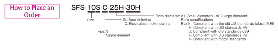
Types of SFS-□S (C)
[Specifications]
| Model | Rated torque[N・m] | False | Max. rotation speed[min -1] | Torsional stiffness[N・m/rad] | Axial stiffness[N/mm] | Moment of inertia[kg・m 2] | Weight[kg] | |
|---|---|---|---|---|---|---|---|---|
| Angle[°] | Shaft[mm] | |||||||
| SFS-05S-C | 15 | 1 | ±0,6 | 25000 | 16000 | 43 | 0,11×10 -3 | 0,30 |
| SFS-06S-C | 30 | 1 | ±0,8 | 20000 | 29000 | 45 | 0,30×10 -3 | 0,50 |
| SFS-08S-C | 60 | 1 | ±1,0 | 17000 | 83000 | 60 | 0,87×10 -3 | 1,00 |
| SFS-09S-C | 135 | 1 | ±1,2 | 15000 | 170000 | 122 | 1,60×10 -3 | 1,40 |
| SFS-10S-C | 190 | 1 | ±1,4 | 13000 | 250000 | 160 | 2,60×10 -3 | 2.10 |
| SFS-12S-C | 340 | 1 | ±1,6 | 11000 | 430000 | 197 | 6,50×10 -3 | 3,40 |
| SFS-14S-C | 600 | 1 | ±1,8 | 9500 | 780000 | 313 | 9,90×10 -3 | 4,90 |
*Max. Rotation speed does not take into account dynamic balance.
*Moment of inertia and mass measured for maximum bore diameter.
[Size]
| Model | d1・d2 | D | N | L | LF | S | F | K | M | |
|---|---|---|---|---|---|---|---|---|---|---|
| Minimum. | Max. | |||||||||
| SFS-05S-C | 8 | 20 | 56 | 32 | 45 | 20 | 5 | 11 | 24 | 4-M5×22 |
| SFS-06S-C | 8 | 25 | 68 | 40 | 56 | 25 | 6 | 10 | 30 | 4-M6×25 |
| SFS-08S-C | 11 | 35 | 82 | 54 | 66 | 30 | 6 | 11 | 38 | 4-M6×29 |
| SFS-09S-C | 11 | 38 | 94 | 58 | 68 | 30 | 8 | 21 | 42 | 4-M8×36 |
| SFS-10S-C | 16 | 42 | 104 | 68 | 80 | 35 | 10 | 16 | 48 | 4-M8×36 |
| SFS-12S-C | 19 | 50 | 126 | 78 | 91 | 40 | 11 | 23 | 54 | 4-M10×45 |
| SFS-14S-C | 22 | 60 | 144 | 88 | 102 | 45 | 12 | 31 | 61 | 4-M12×54 |
* The nominal diameter of a bored bolt M is equal to the quantity minus the nominal diameter of the screw thread multiplied by the nominal length.
[Standard bore diameter]
| Model | Standard hole diameter d1・d2 [mm] | |||||||||||||||||||||||||||
|---|---|---|---|---|---|---|---|---|---|---|---|---|---|---|---|---|---|---|---|---|---|---|---|---|---|---|---|---|
| 8 | 9 | 10 | 11 | 12 | 14 | 15 | 16 | 17 | 18 | 19 | 20 | 22 | 24 | 25 | 28 | 30 | 32 | 35 | 38 | 40 | 42 | 45 | 48 | 50 | 55 | 56 | 60 | |
| SFS-05S-C | ● | ● | ● | ● | ● | ● | ● | ● | ● | ● | ● | ● | ||||||||||||||||
| SFS-06S-C | ● | ● | ● | ● | ● | ● | ● | ● | ● | ● | ● | ● | ● | ● | ● | |||||||||||||
| SFS-08S-C | ● | ● | ● | ● | ● | ● | ● | ● | ● | ● | ● | ● | ● | ● | ● | ● | ||||||||||||
| SFS-09S-C | ● | ● | ● | ● | ● | ● | ● | ● | ● | ● | ● | ● | ● | ● | ● | ● | ● | |||||||||||
| SFS-10S-C | ● | ● | ● | ● | ● | ● | ● | ● | ● | ● | ● | ● | ● | ● | ● | |||||||||||||
| SFS-12S-C | ● | ● | ● | ● | ● | ● | ● | ● | ● | ● | ● | ● | ● | ● | ● | |||||||||||||
| SFS-14S-C | ● | ● | ● | ● | ● | ● | ● | ● | ● | ● | ● | ● | ● | ● | ● | ● | ||||||||||||
* Hole diameters marked with ● are supported as standard hole diameters. See standard hole drilling standards for information.
[Standard hole drilling standards]
| Models comply with the old JIS standard (type 2) JIS B 1301 1959 | The models comply with the new JIS standard (H9) JIS B 1301 1996 | Models comply with the new JIS standard (JS9) JIS B 1301 1996 | ||||||||||||
|---|---|---|---|---|---|---|---|---|---|---|---|---|---|---|
| Nominal hole diameter | Bore diameter(d1・d2) | Keyway height(W1・W2) | Keyway height(T1・T2) | Set the screw hole(M | Nominal hole diameter | Bore diameter(d1・d2) | Keyway height(W1・W2) | Keyway height(T1・T2) | Set the screw hole(M | Nominal hole diameter | Bore diameter(d1・d2) | Keyway height(W1・W2) | Keyway height(T1・T2) | Set the screw hole(M |
| ToleranceH7,H8 | ToleranceE9 | - | - | ToleranceH7,H8 | ToleranceH9 | - | - | ToleranceH7,H8 | ToleranceJS9 | - | - | |||
| 8 | 8 +0,022 0 | - | - | 2-M4 | 8 O'CLOCK | 8 +0,022 0 | 3 +0,025 0 | 9,4 +0,3 0 | 2-M4 | 8J | 8 +0,022 0 | 3 ±0,0125 | 9,4 +0,3 0 | 2-M4 |
| 9 | 9 +0,022 0 | - | - | 2-M4 | 9H | 9 +0,022 0 | 3 +0,025 0 | 10,4 +0,3 0 | 2-M4 | 9J | 9 +0,022 0 | 3 ±0,0125 | 10,4 +0,3 0 | 2-M4 |
| 10 | 10 +0,022 0 | - | - | 2-M4 | 10H | 10 +0,022 0 | 3 +0,025 0 | 11,4 +0,3 0 | 2-M4 | 10J | 10 +0,022 0 | 3 ±0,0125 | 11,4 +0,3 0 | 2-M4 |
| 11 | 11 +0,018 0 | - | - | 2-M4 | 11H | 11 +0,018 0 | 4 +0,030 0 | 12,8 +0,3 0 | 2-M4 | 11J | 11 +0,018 0 | 4 ±0,0150 | 12,8 +0,3 0 | 2-M4 |
| 12 | 12 +0,018 0 | 4 +0,050 +0,020 | 13,5 +0,3 0 | 2-M4 | 12H | 12 +0,018 0 | 4 +0,030 0 | 13,8 +0,3 0 | 2-M4 | 12J | 12 +0,018 0 | 4 ±0,0150 | 13,8 +0,3 0 | 2-M4 |
| 14 | 14 +0,018 0 | 5 +0,050 +0,020 | 16 +0,3 0 | 2-M4 | 14H | 14 +0,018 0 | 5 +0,030 0 | 16,3 +0,3 0 | 2-M4 | 14Y | 14 +0,018 0 | 5 ±0,0150 | 16,3 +0,3 0 | 2-M4 |
| 15 | 15 +0,018 0 | 5 +0,050 +0,020 | 17 +0,3 0 | 2-M4 | 15H | 15 +0,018 0 | 5 +0,030 0 | 17,3 +0,3 0 | 2-M4 | 15J | 15 +0,018 0 | 5 ±0,0150 | 17,3 +0,3 0 | 2-M4 |
| 16 | 16 +0,018 0 | 5 +0,050 +0,020 | 18 +0,3 0 | 2-M4 | 16H | 16 +0,018 0 | 5 +0,030 0 | 18,3 +0,3 0 | 2-M4 | 16J | 16 +0,018 0 | 5 ±0,0150 | 18,3 +0,3 0 | 2-M4 |
| 17 | 17 +0,018 0 | 5 +0,050 +0,020 | 19 +0,3 0 | 2-M4 | 17H | 17 +0,018 0 | 5 +0,030 0 | 19,3 +0,3 0 | 2-M4 | 17J | 17 +0,018 0 | 5 ±0,0150 | 19,3 +0,3 0 | 2-M4 |
| 18 | 18 +0,018 0 | 5 +0,050 +0,020 | 20 +0,3 0 | 2-M4 | 18H | 18 +0,018 0 | 6 +0,030 0 | 20,8 +0,3 0 | 2-M5 | 18J | 18 +0,018 0 | 6 ±0,0150 | 20,8 +0,3 0 | 2-M5 |
| 19 | 19 +0,021 0 | 5 +0,050 +0,020 | 21 +0,3 0 | 2-M4 | 19H | 19 +0,021 0 | 6 +0,030 0 | 21,8 +0,3 0 | 2-M5 | 19J | 19 +0,021 0 | 6 ±0,0150 | 21,8 +0,3 0 | 2-M5 |
| 20 | 20 +0,021 0 | 5 +0,050 +0,020 | 22 +0,3 0 | 2-M4 | 20H | 20 +0,021 0 | 6 +0,030 0 | 22,8 +0,3 0 | 2-M5 | 20J | 20 +0,021 0 | 6 ±0,0150 | 22,8 +0,3 0 | 2-M5 |
| 22 | 22 +0,021 0 | 7 +0,061 +0,025 | 25 +0,3 0 | 2-M6 | 10 p.m | 22 +0,021 0 | 6 +0,030 0 | 24,8 +0,3 0 | 2-M5 | 22J | 22 +0,021 0 | 6 ±0,0150 | 24,8 +0,3 0 | 2-M5 |
| 24 | 24 +0,021 0 | 7 +0,061 +0,025 | 27 +0,3 0 | 2-M6 | 24H | 24 +0,021 0 | 8 +0,036 0 | 27,3 +0,3 0 | 2-M6 | 24J | 24 +0,021 0 | 8 ±0,0180 | 27,3 +0,3 0 | 2-M6 |
| 25 | 25 +0,021 0 | 7 +0,061 +0,025 | 28 +0,3 0 | 2-M6 | 25H | 25 +0,021 0 | 8 +0,036 0 | 28,3 +0,3 0 | 2-M6 | 25J | 25 +0,021 0 | 8 ±0,0180 | 28,3 +0,3 0 | 2-M6 |
| 28 | 28 +0,021 0 | 7 +0,061 +0,025 | 31 +0,3 0 | 2-M6 | 28 hours | 28 +0,021 0 | 8 +0,036 0 | 31,3 +0,3 0 | 2-M6 | 28J | 28 +0,021 0 | 8 ±0,0180 | 31,3 +0,3 0 | 2-M6 |
| 30 | 30 +0,021 0 | 7 +0,061 +0,025 | 33 +0,3 0 | 2-M6 | 30 hours | 30 +0,021 0 | 8 +0,036 0 | 33,3 +0,3 0 | 2-M6 | 30J | 30 +0,021 0 | 8 ±0,0180 | 33,3 +0,3 0 | 2-M6 |
| 32 | 32 +0,025 0 | 10 +0,061 +0,025 | 35,5 +0,3 0 | 2-M8 | 32H | 32 +0,025 0 | 10 +0,036 0 | 35,3 +0,3 0 | 2-M8 | 32J | 32 +0,025 0 | 10 ±0,0180 | 35,3 +0,3 0 | 2-M8 |
| 35 | 35 +0,025 0 | 10 +0,061 +0,025 | 38,5 +0,3 0 | 2-M8 | 35H | 35 +0,025 0 | 10 +0,036 0 | 38,3 +0,3 0 | 2-M8 | 35J | 35 +0,025 0 | 10 ±0,0180 | 38,3 +0,3 0 | 2-M8 |
| 38 | 38 +0,025 0 | 10 +0,061 +0,025 | 41,5 +0,3 0 | 2-M8 | 38H | 38 +0,025 0 | 10 +0,036 0 | 41,3 +0,3 0 | 2-M8 | 38J | 38 +0,025 0 | 10 ±0,0180 | 41,3 +0,3 0 | 2-M8 |
| 40 | 40 +0,025 0 | 10 +0,061 +0,025 | 43,5 +0,3 0 | 2-M8 | 40H | 40 +0,025 0 | 12 +0,043 0 | 43,3 +0,3 0 | 2-M8 | 40J | 40 +0,025 0 | 12 ±0,0215 | 43,3 +0,3 0 | 2-M8 |
| 42 | 42 +0,025 0 | 12 +0,075 +0,032 | 45,5 +0,3 0 | 2-M8 | 42H | 42 +0,025 0 | 12 +0,043 0 | 45,3 +0,3 0 | 2-M8 | 42J | 42 +0,025 0 | 12 ±0,0215 | 45,3 +0,3 0 | 2-M8 |
| 45 | 45 +0,025 0 | 12 +0,075 +0,032 | 48,5 +0,3 0 | 2-M8 | 45H | 45 +0,025 0 | 14 +0,043 0 | 48,8 +0,3 0 | 2-M10 | 45J | 45 +0,025 0 | 14 ±0,0215 | 48,8 +0,3 0 | 2-M10 |
| 48 | 48 +0,025 0 | 12 +0,075 +0,032 | 51,5 +0,3 0 | 2-M8 | 48H | 48 +0,025 0 | 14 +0,043 0 | 51,8 +0,3 0 | 2-M10 | 48J | 48 +0,025 0 | 14 ±0,0215 | 51,8 +0,3 0 | 2-M10 |
| 50 | 50 +0,025 0 | 12 +0,075 +0,032 | 53,5 +0,3 0 | 2-M8 | 50H | 50 +0,025 0 | 14 +0,043 0 | 53,8 +0,3 0 | 2-M10 | 50J | 50 +0,025 0 | 14 ±0,0215 | 53,8 +0,3 0 | 2-M10 |
| 55 | 55 +0,030 0 | 15 +0,075 +0,032 | 60 +0,3 0 | 2-M10 | 55H | 55 +0,030 0 | 16 +0,043 0 | 59,3 +0,3 0 | 2-M10 | 55J | 55 +0,030 0 | 16 ±0,0215 | 59,3 +0,3 0 | 2-M10 |
| 56 | 56 +0,030 0 | 15 +0,075 +0,032 | 61 +0,3 0 | 2-M10 | 56H | 56 +0,030 0 | 16 +0,043 0 | 60,3 +0,3 0 | 2-M10 | 56J | 56 +0,030 0 | 16 ±0,0215 | 60,3 +0,3 0 | 2-M10 |
| 60 | 60 +0,030 0 | 15 +0,075 +0,032 | 65 +0,3 0 | 2-M10 | 60H | 60 +0,030 0 | 18 +0,043 0 | 64,4 +0,3 0 | 2-M10 | 60J | 60 +0,030 0 | 18 ±0,0215 | 64,4 +0,3 0 | 2-M10 |
| The models comply with the new JIS standard (P9) JIS B 1301 1996 | Model conforms to JIS C 4210 2001 engine standard | ||||||||
|---|---|---|---|---|---|---|---|---|---|
| Nominal hole diameter | Bore diameter(d1・d2) | Keyway width(W1・W2) | Keyway height(T1・T2) | Set the screw hole(M | Nominal hole diameter | Bore diameter(d1・d2) | Keyway width(W1・W2) | Keyway height(T1・T2) | Set the screw hole(M |
| ToleranceH7,H8 | ToleranceP9 | + 0,30 0 | - | - | ToleranceG7,F7 | ToleranceH9 | - | ||
| 8P | 8 +0,022 | 3 -0,006 -0,031 | 9,4 +0,3 0 | 2-M4 | - | - | - | - | - |
| 9P | 9 +0,022 | 3 -0,006 -0,031 | 10,4 +0,3 0 | 2-M4 | - | - | - | - | - |
| 10P | 10 +0,022 | 3 -0,006 -0,031 | 11,4 +0,3 0 | 2-M4 | - | - | - | - | - |
| 11P | 11 +0,018 | 4 -0,042 -0,012 | 12,8 +0,3 0 | 2-M4 | - | - | - | - | - |
| 12P | 12 +0,018 | 4 -0,042 -0,012 | 13,8 +0,3 0 | 2-M4 | - | - | - | - | - |
| 14P | 14 +0,018 | 5 -0,042 -0,012 | 16,3 +0,3 0 | 2-M4 | 14N | 14 +0,024 +0,006 | 5 +0,030 | 16,3 +0,3 0 | 2-M4 |
| 15P | 15 +0,018 | 5 -0,042 -0,012 | 17,3 +0,3 0 | 2-M4 | - | - | - | - | - |
| 16P | 16 +0,018 | 5 -0,042 -0,012 | 18,3 +0,3 0 | 2-M4 | - | - | - | - | - |
| 17P | 17 +0,018 | 5 -0,042 -0,012 | 19,3 +0,3 0 | 2-M4 | - | - | - | - | - |
| 18P | 18 +0,018 | 6 -0,042 -0,012 | 20,8 +0,3 0 | 2-M5 | - | - | - | - | - |
| 19P | 19 +0,021 | 6 -0,042 -0,012 | 21,8 +0,3 0 | 2-M5 | 19N | 19 +0,028 +0,007 | 6 +0,030 | 21,8 +0,3 0 | 2-M5 |
| 20P | 20 +0,021 | 6 -0,042 -0,012 | 22,8 +0,3 0 | 2-M5 | - | - | - | - | - |
| 22P | 22 +0,021 | 6 -0,042 -0,012 | 24,8 +0,3 0 | 2-M5 | - | - | - | - | - |
| 24P | 24 +0,021 | 8 -0,051 -0,015 | 27,3 +0,3 0 | 2-M6 | 24N | 24 +0,028 +0,007 | 8 +0,036 | 27,3 +0,3 0 | 2-M6 |
| 25P | 25 +0,021 | 8 -0,051 -0,015 | 28,3 +0,3 0 | 2-M6 | - | - | - | - | - |
| 28P | 28 +0,021 | 8 -0,051 -0,015 | 31,3 +0,3 0 | 2-M6 | 28N | 28 +0,028 +0,007 | 8 +0,036 | 31,3 +0,3 0 | 2-M6 |
| 30P | 30 +0,021 | 8 -0,051 -0,015 | 33,3 +0,3 0 | 2-M6 | - | - | - | - | - |
| 32P | 32 +0,025 | 10 -0,051 -0,015 | 35,3 +0,3 0 | 2-M8 | - | - | - | ||
| 35P | 35 +0,025 | 10 -0,051 -0,015 | 38,3 +0,3 0 | 2-M8 | - | - | - | - | |
| 38P | 38 +0,025 | 10 -0,051 -0,015 | 41,3 +0,3 0 | 2-M8 | 38N | 38 +0,050 +0,025 | 10 +0,036 | 41,3 +0,3 0 | 2-M8 |
| 40P | 40 +0,025 | 12 -0,061 -0,018 | 43,3 +0,3 0 | 2-M8 | - | - | - | - | - |
| 42P | 42 +0,025 | 12 -0,061 -0,018 | 45,3 +0,3 0 | 2-M8 | 42N | 42 +0,050 +0,025 | 12 +0,043 | 45,3 +0,3 0 | 2-M8 |
| 45P | 45 +0,025 | 14 -0,061 -0,018 | 48,8 +0,3 0 | 2-M10 | - | - | - | - | - |
| 48 P | 48 +0,025 | 14 -0,061 -0,018 | 51,8 +0,3 0 | 2-M10 | 48N | 48 +0,050 +0,025 | 14 +0,043 | 51,8 +0,3 0 | 2-M10 |
| 50P | 50 +0,025 | 14 -0,061 -0,018 | 53,8 +0,3 0 | 2-M10 | - | - | - | - | - |
| 55P | 55 +0,030 | 16 -0,061 -0,018 | 59,3 +0,3 0 | 2-M10 | 55N | 55 +0,060 +0,030 | 16 +0,043 | 59,3 +0,3 0 | 2-M10 |
| 56P | 56 +0,030 | 16 -0,061 -0,018 | 60,3 +0,3 0 | 2-M10 | - | - | - | - | - |
| 60P | 60 +0,030 | 18 -0,061 -0,018 | 64,4 +0,3 0 | 2-M10 | 60N | 60 +0,060 +0,030 | 18 +0,043 | 64,4 +0,3 0 | 2-M10 |
※The positions of the set screw and the keyway are not on the same plane.
※Screw set is included in the product.
※Positioning accuracy when milling keyway is determined by sight.
※Contact Miki Pulley when keyway positioning accuracy is required for a specific flange shaft.
※Refer to the technical documentation at the end of this volume for standard dimensions for borehole drilling in addition to those stated here.
[Set screw position]
| Model | Distance from edge [mm] |
|---|---|
| SFS-05 | 7 |
| SFS-06 | 9 |
| SFS-08 | 10 |
| SFS-09 | 10 |
| SFS-10 | 12 |
| SFS-12 | 12 |
| SFS-14 | 15 |
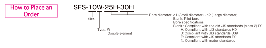
Types of SFS-□W
[Specifications]
| Model | Rated torque[N・m] | False | Max. rotation speed[min -1] | Torsional stiffness[N・m/rad] | Axial stiffness[N/mm] | Moment of inertia[kg・m 2] | Weight[kg] | ||
|---|---|---|---|---|---|---|---|---|---|
| Song song[mm] | Angle[°] | Shaft[mm] | |||||||
| SFS-05W | 20 | 0,2 | 1(One side) | ±1,2 | 10000 | 8000 | 21 | 0,14×10 -3 | 0,40 |
| SFS-06W | 40 | 0,3 | 1(One side) | ±1,6 | 8000 | 14000 | 22 | 0,41×10 -3 | 0,70 |
| SFS-08W | 80 | 0,3 | 1(One side) | ±2,0 | 6800 | 41000 | 30 | 1,10×10 -3 | 1h30 |
| SFS-09W | 180 | 0,5 | 1(One side) | ±2,4 | 6000 | 85000 | 61 | 2,20×10 -3 | 2.10 |
| SFS-10W | 250 | 0,5 | 1(One side) | ±2,8 | 5200 | 125000 | 80 | 3,60×10 -3 | 2,80 |
| SFS-12W | 450 | 0,6 | 1(One side) | ±3,2 | 4400 | 215000 | 98 | 9,20×10 -3 | 4,90 |
| SFS-14W | 800 | 0,7 | 1(One side) | ±3,6 | 3800 | 390000 | 156 | 15,00×10 -3 | 7.10 |
*Max. Rotation speed does not take into account dynamic balance.
*Moment of inertia and mass measured for maximum bore diameter.
[Size]

| Model | d1・d2 | D | N | L | LF | LP | S | F | d3 | K | M | ||
|---|---|---|---|---|---|---|---|---|---|---|---|---|---|
| pilot drill hole | Minimum. | Max. | |||||||||||
| SFS-05W | 7 | 8 | 20 | 56 | 32 | 58 | 20 | 8 | 5 | 4 | 20 | 24 | 8-M5×15 |
| SFS-06W | 7 | 8 | 25 | 68 | 40 | 74 | 25 | 12 | 6 | 3 | 24 | 30 | 8-M6×18 |
| SFS-08W | 10 | 11 | 35 | 82 | 54 | 84 | 30 | 12 | 6 | 2 | 28 | 38 | 8-M6×20 |
| SFS-09W | 10 | 11 | 38 | 94 | 58 | 98 | 30 | 22 | 8 | 12 | 32 | 42 | 8-M8×27 |
| SFS-10W | 15 | 16 | 42 | 104 | 68 | 110 | 35 | 20 | 10 | 7 | 34 | 48 | 8-M8×27 |
| SFS-12W | 18 | 19 | 50 | 126 | 78 | 127 | 40 | 25 | 11 | 10 | 40 | 54 | 8-M10×32 |
| SFS-14W | 20 | 22 | 60 | 144 | 88 | 144 | 45 | 30 | 12 | 15 | 46 | 61 | 8-M12×38 |
* Pilot holes must be drilled into the part.
* The nominal diameter of a bored bolt M is equal to the quantity minus the nominal diameter of the screw thread multiplied by the nominal length.
[Standard bore diameter]
| Model | Standard hole diameter d1・d2 [mm] | |||||||||||||||||||||||||||
|---|---|---|---|---|---|---|---|---|---|---|---|---|---|---|---|---|---|---|---|---|---|---|---|---|---|---|---|---|
| 8 | 9 | 10 | 11 | 12 | 14 | 15 | 16 | 17 | 18 | 19 | 20 | 22 | 24 | 25 | 28 | 30 | 32 | 35 | 38 | 40 | 42 | 45 | 48 | 50 | 55 | 56 | 60 | |
| SFS-05W | ● | ● | ● | ● | ● | ● | ● | ● | ● | ● | ● | ● | ||||||||||||||||
| SFS-06W | ● | ● | ● | ● | ● | ● | ● | ● | ● | ● | ● | ● | ● | ● | ● | |||||||||||||
| SFS-08W | ● | ● | ● | ● | ● | ● | ● | ● | ● | ● | ● | ● | ● | ● | ● | ● | ||||||||||||
| SFS-09W | ● | ● | ● | ● | ● | ● | ● | ● | ● | ● | ● | ● | ● | ● | ● | ● | ● | |||||||||||
| SFS-10W | ● | ● | ● | ● | ● | ● | ● | ● | ● | ● | ● | ● | ● | ● | ● | |||||||||||||
| SFS-12W | ● | ● | ● | ● | ● | ● | ● | ● | ● | ● | ● | ● | ● | ● | ● | |||||||||||||
| SFS-14W | ● | ● | ● | ● | ● | ● | ● | ● | ● | ● | ● | ● | ● | ● | ● | ● | ||||||||||||
* Hole diameters marked with ● are supported as standard hole diameters. See standard hole drilling standards for information.
[Standard hole drilling standards]
| Models comply with the old JIS standard (type 2) JIS B 1301 1959 | The models comply with the new JIS standard (H9) JIS B 1301 1996 | Models comply with the new JIS standard (JS9) JIS B 1301 1996 | ||||||||||||
|---|---|---|---|---|---|---|---|---|---|---|---|---|---|---|
| Nominal hole diameter | Bore diameter(d1・d2) | Keyway height(W1・W2) | Keyway height(T1・T2) | Set the screw hole(M | Nominal hole diameter | Bore diameter(d1・d2) | Keyway height(W1・W2) | Keyway height(T1・T2) | Set the screw hole(M | Nominal hole diameter | Bore diameter(d1・d2) | Keyway height(W1・W2) | Keyway height(T1・T2) | Set the screw hole(M |
| ToleranceH7,H8 | ToleranceE9 | - | - | ToleranceH7,H8 | ToleranceH9 | - | - | ToleranceH7,H8 | ToleranceJS9 | - | - | |||
| 8 | 8 +0,022 0 | - | - | 2-M4 | 8 O'CLOCK | 8 +0,022 0 | 3 +0,025 0 | 9,4 +0,3 0 | 2-M4 | 8J | 8 +0,022 0 | 3 ±0,0125 | 9,4 +0,3 0 | 2-M4 |
| 9 | 9 +0,022 0 | - | - | 2-M4 | 9H | 9 +0,022 0 | 3 +0,025 0 | 10,4 +0,3 0 | 2-M4 | 9J | 9 +0,022 0 | 3 ±0,0125 | 10,4 +0,3 0 | 2-M4 |
| 10 | 10 +0,022 0 | - | - | 2-M4 | 10H | 10 +0,022 0 | 3 +0,025 0 | 11,4 +0,3 0 | 2-M4 | 10J | 10 +0,022 0 | 3 ±0,0125 | 11,4 +0,3 0 | 2-M4 |
| 11 | 11 +0,018 0 | - | - | 2-M4 | 11H | 11 +0,018 0 | 4 +0,030 0 | 12,8 +0,3 0 | 2-M4 | 11J | 11 +0,018 0 | 4 ±0,0150 | 12,8 +0,3 0 | 2-M4 |
| 12 | 12 +0,018 0 | 4 +0,050 +0,020 | 13,5 +0,3 0 | 2-M4 | 12H | 12 +0,018 0 | 4 +0,030 0 | 13,8 +0,3 0 | 2-M4 | 12J | 12 +0,018 0 | 4 ±0,0150 | 13,8 +0,3 0 | 2-M4 |
| 14 | 14 +0,018 0 | 5 +0,050 +0,020 | 16 +0,3 0 | 2-M4 | 14H | 14 +0,018 0 | 5 +0,030 0 | 16,3 +0,3 0 | 2-M4 | 14Y | 14 +0,018 0 | 5 ±0,0150 | 16,3 +0,3 0 | 2-M4 |
| 15 | 15 +0,018 0 | 5 +0,050 +0,020 | 17 +0,3 0 | 2-M4 | 15H | 15 +0,018 0 | 5 +0,030 0 | 17,3 +0,3 0 | 2-M4 | 15J | 15 +0,018 0 | 5 ±0,0150 | 17,3 +0,3 0 | 2-M4 |
| 16 | 16 +0,018 0 | 5 +0,050 +0,020 | 18 +0,3 0 | 2-M4 | 16H | 16 +0,018 0 | 5 +0,030 0 | 18,3 +0,3 0 | 2-M4 | 16J | 16 +0,018 0 | 5 ±0,0150 | 18,3 +0,3 0 | 2-M4 |
| 17 | 17 +0,018 0 | 5 +0,050 +0,020 | 19 +0,3 0 | 2-M4 | 17H | 17 +0,018 0 | 5 +0,030 0 | 19,3 +0,3 0 | 2-M4 | 17J | 17 +0,018 0 | 5 ±0,0150 | 19,3 +0,3 0 | 2-M4 |
| 18 | 18 +0,018 0 | 5 +0,050 +0,020 | 20 +0,3 0 | 2-M4 | 18H | 18 +0,018 0 | 6 +0,030 0 | 20,8 +0,3 0 | 2-M5 | 18J | 18 +0,018 0 | 6 ±0,0150 | 20,8 +0,3 0 | 2-M5 |
| 19 | 19 +0,021 0 | 5 +0,050 +0,020 | 21 +0,3 0 | 2-M4 | 19H | 19 +0,021 0 | 6 +0,030 0 | 21,8 +0,3 0 | 2-M5 | 19J | 19 +0,021 0 | 6 ±0,0150 | 21,8 +0,3 0 | 2-M5 |
| 20 | 20 +0,021 0 | 5 +0,050 +0,020 | 22 +0,3 0 | 2-M4 | 20H | 20 +0,021 0 | 6 +0,030 0 | 22,8 +0,3 0 | 2-M5 | 20J | 20 +0,021 0 | 6 ±0,0150 | 22,8 +0,3 0 | 2-M5 |
| 22 | 22 +0,021 0 | 7 +0,061 +0,025 | 25 +0,3 0 | 2-M6 | 10 p.m | 22 +0,021 0 | 6 +0,030 0 | 24,8 +0,3 0 | 2-M5 | 22J | 22 +0,021 0 | 6 ±0,0150 | 24,8 +0,3 0 | 2-M5 |
| 24 | 24 +0,021 0 | 7 +0,061 +0,025 | 27 +0,3 0 | 2-M6 | 24H | 24 +0,021 0 | 8 +0,036 0 | 27,3 +0,3 0 | 2-M6 | 24J | 24 +0,021 0 | 8 ±0,0180 | 27,3 +0,3 0 | 2-M6 |
| 25 | 25 +0,021 0 | 7 +0,061 +0,025 | 28 +0,3 0 | 2-M6 | 25H | 25 +0,021 0 | 8 +0,036 0 | 28,3 +0,3 0 | 2-M6 | 25J | 25 +0,021 0 | 8 ±0,0180 | 28,3 +0,3 0 | 2-M6 |
| 28 | 28 +0,021 0 | 7 +0,061 +0,025 | 31 +0,3 0 | 2-M6 | 28 hours | 28 +0,021 0 | 8 +0,036 0 | 31,3 +0,3 0 | 2-M6 | 28J | 28 +0,021 0 | 8 ±0,0180 | 31,3 +0,3 0 | 2-M6 |
| 30 | 30 +0,021 0 | 7 +0,061 +0,025 | 33 +0,3 0 | 2-M6 | 30 hours | 30 +0,021 0 | 8 +0,036 0 | 33,3 +0,3 0 | 2-M6 | 30J | 30 +0,021 0 | 8 ±0,0180 | 33,3 +0,3 0 | 2-M6 |
| 32 | 32 +0,025 0 | 10 +0,061 +0,025 | 35,5 +0,3 0 | 2-M8 | 32H | 32 +0,025 0 | 10 +0,036 0 | 35,3 +0,3 0 | 2-M8 | 32J | 32 +0,025 0 | 10 ±0,0180 | 35,3 +0,3 0 | 2-M8 |
| 35 | 35 +0,025 0 | 10 +0,061 +0,025 | 38,5 +0,3 0 | 2-M8 | 35H | 35 +0,025 0 | 10 +0,036 0 | 38,3 +0,3 0 | 2-M8 | 35J | 35 +0,025 0 | 10 ±0,0180 | 38,3 +0,3 0 | 2-M8 |
| 38 | 38 +0,025 0 | 10 +0,061 +0,025 | 41,5 +0,3 0 | 2-M8 | 38H | 38 +0,025 0 | 10 +0,036 0 | 41,3 +0,3 0 | 2-M8 | 38J | 38 +0,025 0 | 10 ±0,0180 | 41,3 +0,3 0 | 2-M8 |
| 40 | 40 +0,025 0 | 10 +0,061 +0,025 | 43,5 +0,3 0 | 2-M8 | 40H | 40 +0,025 0 | 12 +0,043 0 | 43,3 +0,3 0 | 2-M8 | 40J | 40 +0,025 0 | 12 ±0,0215 | 43,3 +0,3 0 | 2-M8 |
| 42 | 42 +0,025 0 | 12 +0,075 +0,032 | 45,5 +0,3 0 | 2-M8 | 42H | 42 +0,025 0 | 12 +0,043 0 | 45,3 +0,3 0 | 2-M8 | 42J | 42 +0,025 0 | 12 ±0,0215 | 45,3 +0,3 0 | 2-M8 |
| 45 | 45 +0,025 0 | 12 +0,075 +0,032 | 48,5 +0,3 0 | 2-M8 | 45H | 45 +0,025 0 | 14 +0,043 0 | 48,8 +0,3 0 | 2-M10 | 45J | 45 +0,025 0 | 14 ±0,0215 | 48,8 +0,3 0 | 2-M10 |
| 48 | 48 +0,025 0 | 12 +0,075 +0,032 | 51,5 +0,3 0 | 2-M8 | 48H | 48 +0,025 0 | 14 +0,043 0 | 51,8 +0,3 0 | 2-M10 | 48J | 48 +0,025 0 | 14 ±0,0215 | 51,8 +0,3 0 | 2-M10 |
| 50 | 50 +0,025 0 | 12 +0,075 +0,032 | 53,5 +0,3 0 | 2-M8 | 50H | 50 +0,025 0 | 14 +0,043 0 | 53,8 +0,3 0 | 2-M10 | 50J | 50 +0,025 0 | 14 ±0,0215 | 53,8 +0,3 0 | 2-M10 |
| 55 | 55 +0,030 0 | 15 +0,075 +0,032 | 60 +0,3 0 | 2-M10 | 55H | 55 +0,030 0 | 16 +0,043 0 | 59,3 +0,3 0 | 2-M10 | 55J | 55 +0,030 0 | 16 ±0,0215 | 59,3 +0,3 0 | 2-M10 |
| 56 | 56 +0,030 0 | 15 +0,075 +0,032 | 61 +0,3 0 | 2-M10 | 56H | 56 +0,030 0 | 16 +0,043 0 | 60,3 +0,3 0 | 2-M10 | 56J | 56 +0,030 0 | 16 ±0,0215 | 60,3 +0,3 0 | 2-M10 |
| 60 | 60 +0,030 0 | 15 +0,075 +0,032 | 65 +0,3 0 | 2-M10 | 60H | 60 +0,030 0 | 18 +0,043 0 | 64,4 +0,3 0 | 2-M10 | 60J | 60 +0,030 0 | 18 ±0,0215 | 64,4 +0,3 0 | 2-M10 |
| The models comply with the new JIS standard (P9) JIS B 1301 1996 | Model conforms to JIS C 4210 2001 engine standard | ||||||||
|---|---|---|---|---|---|---|---|---|---|
| Nominal hole diameter | Bore diameter(d1・d2) | Keyway width(W1・W2) | Keyway height(T1・T2) | Set the screw hole(M | Nominal hole diameter | Bore diameter(d1・d2) | Keyway width(W1・W2) | Keyway height(T1・T2) | Set the screw hole(M |
| ToleranceH7,H8 | ToleranceP9 | + 0,30 0 | - | - | ToleranceG7,F7 | ToleranceH9 | - | ||
| 8P | 8 +0,022 | 3 -0,006 -0,031 | 9,4 +0,3 0 | 2-M4 | - | - | - | - | - |
| 9P | 9 +0,022 | 3 -0,006 -0,031 | 10,4 +0,3 0 | 2-M4 | - | - | - | - | - |
| 10P | 10 +0,022 | 3 -0,006 -0,031 | 11,4 +0,3 0 | 2-M4 | - | - | - | - | - |
| 11P | 11 +0,018 | 4 -0,042 -0,012 | 12,8 +0,3 0 | 2-M4 | - | - | - | - | - |
| 12P | 12 +0,018 | 4 -0,042 -0,012 | 13,8 +0,3 0 | 2-M4 | - | - | - | - | - |
| 14P | 14 +0,018 | 5 -0,042 -0,012 | 16,3 +0,3 0 | 2-M4 | 14N | 14 +0,024 +0,006 | 5 +0,030 | 16,3 +0,3 0 | 2-M4 |
| 15P | 15 +0,018 | 5 -0,042 -0,012 | 17,3 +0,3 0 | 2-M4 | - | - | - | - | - |
| 16P | 16 +0,018 | 5 -0,042 -0,012 | 18,3 +0,3 0 | 2-M4 | - | - | - | - | - |
| 17P | 17 +0,018 | 5 -0,042 -0,012 | 19,3 +0,3 0 | 2-M4 | - | - | - | - | - |
| 18P | 18 +0,018 | 6 -0,042 -0,012 | 20,8 +0,3 0 | 2-M5 | - | - | - | - | - |
| 19P | 19 +0,021 | 6 -0,042 -0,012 | 21,8 +0,3 0 | 2-M5 | 19N | 19 +0,028 +0,007 | 6 +0,030 | 21,8 +0,3 0 | 2-M5 |
| 20P | 20 +0,021 | 6 -0,042 -0,012 | 22,8 +0,3 0 | 2-M5 | - | - | - | - | - |
| 22P | 22 +0,021 | 6 -0,042 -0,012 | 24,8 +0,3 0 | 2-M5 | - | - | - | - | - |
| 24P | 24 +0,021 | 8 -0,051 -0,015 | 27,3 +0,3 0 | 2-M6 | 24N | 24 +0,028 +0,007 | 8 +0,036 | 27,3 +0,3 0 | 2-M6 |
| 25P | 25 +0,021 | 8 -0,051 -0,015 | 28,3 +0,3 0 | 2-M6 | - | - | - | - | - |
| 28P | 28 +0,021 | 8 -0,051 -0,015 | 31,3 +0,3 0 | 2-M6 | 28N | 28 +0,028 +0,007 | 8 +0,036 | 31,3 +0,3 0 | 2-M6 |
| 30P | 30 +0,021 | 8 -0,051 -0,015 | 33,3 +0,3 0 | 2-M6 | - | - | - | - | - |
| 32P | 32 +0,025 | 10 -0,051 -0,015 | 35,3 +0,3 0 | 2-M8 | - | - | - | ||
| 35P | 35 +0,025 | 10 -0,051 -0,015 | 38,3 +0,3 0 | 2-M8 | - | - | - | - | |
| 38P | 38 +0,025 | 10 -0,051 -0,015 | 41,3 +0,3 0 | 2-M8 | 38N | 38 +0,050 +0,025 | 10 +0,036 | 41,3 +0,3 0 | 2-M8 |
| 40P | 40 +0,025 | 12 -0,061 -0,018 | 43,3 +0,3 0 | 2-M8 | - | - | - | - | - |
| 42P | 42 +0,025 | 12 -0,061 -0,018 | 45,3 +0,3 0 | 2-M8 | 42N | 42 +0,050 +0,025 | 12 +0,043 | 45,3 +0,3 0 | 2-M8 |
| 45P | 45 +0,025 | 14 -0,061 -0,018 | 48,8 +0,3 0 | 2-M10 | - | - | - | - | - |
| 48 P | 48 +0,025 | 14 -0,061 -0,018 | 51,8 +0,3 0 | 2-M10 | 48N | 48 +0,050 +0,025 | 14 +0,043 | 51,8 +0,3 0 | 2-M10 |
| 50P | 50 +0,025 | 14 -0,061 -0,018 | 53,8 +0,3 0 | 2-M10 | - | - | - | - | - |
| 55P | 55 +0,030 | 16 -0,061 -0,018 | 59,3 +0,3 0 | 2-M10 | 55N | 55 +0,060 +0,030 | 16 +0,043 | 59,3 +0,3 0 | 2-M10 |
| 56P | 56 +0,030 | 16 -0,061 -0,018 | 60,3 +0,3 0 | 2-M10 | - | - | - | - | - |
| 60P | 60 +0,030 | 18 -0,061 -0,018 | 64,4 +0,3 0 | 2-M10 | 60N | 60 +0,060 +0,030 | 18 +0,043 | 64,4 +0,3 0 | 2-M10 |
※The positions of the set screw and the keyway are not on the same plane.
※Screw set is included in the product.
※Positioning accuracy when milling keyway is determined by sight.
※Contact Miki Pulley when keyway positioning accuracy is required for a specific flange shaft.
※Refer to the technical documentation at the end of this volume for standard dimensions for borehole drilling in addition to those stated here.
[Set screw position]
| Model | Distance from edge [mm] |
|---|---|
| SFS-05 | 7 |
| SFS-06 | 9 |
| SFS-08 | 10 |
| SFS-09 | 10 |
| SFS-10 | 12 |
| SFS-12 | 12 |
| SFS-14 | 15 |
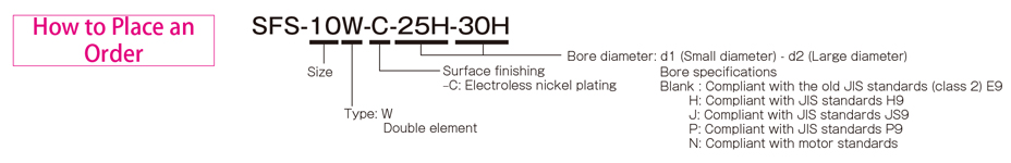
Types SFS-□W (C)
[Specifications]
| Model | Rated torque[N・m] | False | Max. rotation speed[min -1] | Torsional stiffness[N・m/rad] | Axial stiffness[N/mm] | Moment of inertia[kg・m 2] | Weight[kg] | ||
|---|---|---|---|---|---|---|---|---|---|
| Song song[mm] | Angle[°] | Shaft[mm] | |||||||
| SFS-05W-C | 15 | 0,2 | 1(One side) | ±1,2 | 10000 | 8000 | 21 | 0,14×10 -3 | 0,40 |
| SFS-06W-C | 30 | 0,3 | 1(One side) | ±1,6 | 8000 | 14000 | 22 | 0,41×10 -3 | 0,70 |
| SFS-08W-C | 60 | 0,3 | 1(One side) | ±2,0 | 6800 | 41000 | 30 | 1,10×10 -3 | 1h30 |
| SFS-09W-C | 135 | 0,5 | 1(One side) | ±2,4 | 6000 | 85000 | 61 | 2,20×10 -3 | 2.10 |
| SFS-10W-C | 190 | 0,5 | 1(One side) | ±2,8 | 5200 | 125000 | 80 | 3,60×10 -3 | 2,80 |
| SFS-12W-C | 340 | 0,6 | 1(One side) | ±3,2 | 4400 | 215000 | 98 | 9,20×10 -3 | 4,90 |
| SFS-14W-C | 600 | 0,7 | 1(One side) | ±3,6 | 3800 | 390000 | 156 | 15,00×10 -3 | 7.10 |
*Max. Rotation speed does not take into account dynamic balance.
*Moment of inertia and mass measured for maximum bore diameter.
[Size]
| Model | d1・d2 | D | N | L | LF | LP | S | F | d3 | K | M | |
|---|---|---|---|---|---|---|---|---|---|---|---|---|
| Minimum. | Max. | |||||||||||
| SFS-05W-C | 8 | 20 | 56 | 32 | 58 | 20 | 8 | 5 | 4 | 20 | 24 | 8-M5×15 |
| SFS-06W-C | 8 | 25 | 68 | 40 | 74 | 25 | 12 | 6 | 3 | 24 | 30 | 8-M6×18 |
| SFS-08W-C | 11 | 35 | 82 | 54 | 84 | 30 | 12 | 6 | 2 | 28 | 38 | 8-M6×20 |
| SFS-09W-C | 11 | 38 | 94 | 58 | 98 | 30 | 22 | 8 | 12 | 32 | 42 | 8-M8×27 |
| SFS-10W-C | 16 | 42 | 104 | 68 | 110 | 35 | 20 | 10 | 7 | 34 | 48 | 8-M8×27 |
| SFS-12W-C | 19 | 50 | 126 | 78 | 127 | 40 | 25 | 11 | 10 | 40 | 54 | 8-M10×32 |
| SFS-14W-C | 22 | 60 | 144 | 88 | 144 | 45 | 30 | 12 | 15 | 46 | 61 | 8-M12×38 |
* The nominal diameter of a bored bolt M is equal to the quantity minus the nominal diameter of the screw thread multiplied by the nominal length.
[Standard bore diameter]
| Model | Standard hole diameter d1・d2 [mm] | |||||||||||||||||||||||||||
|---|---|---|---|---|---|---|---|---|---|---|---|---|---|---|---|---|---|---|---|---|---|---|---|---|---|---|---|---|
| 8 | 9 | 10 | 11 | 12 | 14 | 15 | 16 | 17 | 18 | 19 | 20 | 22 | 24 | 25 | 28 | 30 | 32 | 35 | 38 | 40 | 42 | 45 | 48 | 50 | 55 | 56 | 60 | |
| SFS-05W-C | ● | ● | ● | ● | ● | ● | ● | ● | ● | ● | ● | ● | ||||||||||||||||
| SFS-06W-C | ● | ● | ● | ● | ● | ● | ● | ● | ● | ● | ● | ● | ● | ● | ● | |||||||||||||
| SFS-08W-C | ● | ● | ● | ● | ● | ● | ● | ● | ● | ● | ● | ● | ● | ● | ● | ● | ||||||||||||
| SFS-09W-C | ● | ● | ● | ● | ● | ● | ● | ● | ● | ● | ● | ● | ● | ● | ● | ● | ● | |||||||||||
| SFS-10W-C | ● | ● | ● | ● | ● | ● | ● | ● | ● | ● | ● | ● | ● | ● | ● | |||||||||||||
| SFS-12W-C | ● | ● | ● | ● | ● | ● | ● | ● | ● | ● | ● | ● | ● | ● | ● | |||||||||||||
| SFS-14W-C | ● | ● | ● | ● | ● | ● | ● | ● | ● | ● | ● | ● | ● | ● | ● | ● | ||||||||||||
* Hole diameters marked with ● are supported as standard hole diameters. See standard hole drilling standards for information.
[Standard hole drilling standards]
| Models comply with the old JIS standard (type 2) JIS B 1301 1959 | The models comply with the new JIS standard (H9) JIS B 1301 1996 | Models comply with the new JIS standard (JS9) JIS B 1301 1996 | ||||||||||||
|---|---|---|---|---|---|---|---|---|---|---|---|---|---|---|
| Nominal hole diameter | Bore diameter(d1・d2) | Keyway height(W1・W2) | Keyway height(T1・T2) | Set the screw hole(M | Nominal hole diameter | Bore diameter(d1・d2) | Keyway height(W1・W2) | Keyway height(T1・T2) | Set the screw hole(M | Nominal hole diameter | Bore diameter(d1・d2) | Keyway height(W1・W2) | Keyway height(T1・T2) | Set the screw hole(M |
| ToleranceH7,H8 | ToleranceE9 | - | - | ToleranceH7,H8 | ToleranceH9 | - | - | ToleranceH7,H8 | ToleranceJS9 | - | - | |||
| 8 | 8 +0,022 0 | - | - | 2-M4 | 8 O'CLOCK | 8 +0,022 0 | 3 +0,025 0 | 9,4 +0,3 0 | 2-M4 | 8J | 8 +0,022 0 | 3 ±0,0125 | 9,4 +0,3 0 | 2-M4 |
| 9 | 9 +0,022 0 | - | - | 2-M4 | 9H | 9 +0,022 0 | 3 +0,025 0 | 10,4 +0,3 0 | 2-M4 | 9J | 9 +0,022 0 | 3 ±0,0125 | 10,4 +0,3 0 | 2-M4 |
| 10 | 10 +0,022 0 | - | - | 2-M4 | 10H | 10 +0,022 0 | 3 +0,025 0 | 11,4 +0,3 0 | 2-M4 | 10J | 10 +0,022 0 | 3 ±0,0125 | 11,4 +0,3 0 | 2-M4 |
| 11 | 11 +0,018 0 | - | - | 2-M4 | 11H | 11 +0,018 0 | 4 +0,030 0 | 12,8 +0,3 0 | 2-M4 | 11J | 11 +0,018 0 | 4 ±0,0150 | 12,8 +0,3 0 | 2-M4 |
| 12 | 12 +0,018 0 | 4 +0,050 +0,020 | 13,5 +0,3 0 | 2-M4 | 12H | 12 +0,018 0 | 4 +0,030 0 | 13,8 +0,3 0 | 2-M4 | 12J | 12 +0,018 0 | 4 ±0,0150 | 13,8 +0,3 0 | 2-M4 |
| 14 | 14 +0,018 0 | 5 +0,050 +0,020 | 16 +0,3 0 | 2-M4 | 14H | 14 +0,018 0 | 5 +0,030 0 | 16,3 +0,3 0 | 2-M4 | 14Y | 14 +0,018 0 | 5 ±0,0150 | 16,3 +0,3 0 | 2-M4 |
| 15 | 15 +0,018 0 | 5 +0,050 +0,020 | 17 +0,3 0 | 2-M4 | 15H | 15 +0,018 0 | 5 +0,030 0 | 17,3 +0,3 0 | 2-M4 | 15J | 15 +0,018 0 | 5 ±0,0150 | 17,3 +0,3 0 | 2-M4 |
| 16 | 16 +0,018 0 | 5 +0,050 +0,020 | 18 +0,3 0 | 2-M4 | 16H | 16 +0,018 0 | 5 +0,030 0 | 18,3 +0,3 0 | 2-M4 | 16J | 16 +0,018 0 | 5 ±0,0150 | 18,3 +0,3 0 | 2-M4 |
| 17 | 17 +0,018 0 | 5 +0,050 +0,020 | 19 +0,3 0 | 2-M4 | 17H | 17 +0,018 0 | 5 +0,030 0 | 19,3 +0,3 0 | 2-M4 | 17J | 17 +0,018 0 | 5 ±0,0150 | 19,3 +0,3 0 | 2-M4 |
| 18 | 18 +0,018 0 | 5 +0,050 +0,020 | 20 +0,3 0 | 2-M4 | 18H | 18 +0,018 0 | 6 +0,030 0 | 20,8 +0,3 0 | 2-M5 | 18J | 18 +0,018 0 | 6 ±0,0150 | 20,8 +0,3 0 | 2-M5 |
| 19 | 19 +0,021 0 | 5 +0,050 +0,020 | 21 +0,3 0 | 2-M4 | 19H | 19 +0,021 0 | 6 +0,030 0 | 21,8 +0,3 0 | 2-M5 | 19J | 19 +0,021 0 | 6 ±0,0150 | 21,8 +0,3 0 | 2-M5 |
| 20 | 20 +0,021 0 | 5 +0,050 +0,020 | 22 +0,3 0 | 2-M4 | 20H | 20 +0,021 0 | 6 +0,030 0 | 22,8 +0,3 0 | 2-M5 | 20J | 20 +0,021 0 | 6 ±0,0150 | 22,8 +0,3 0 | 2-M5 |
| 22 | 22 +0,021 0 | 7 +0,061 +0,025 | 25 +0,3 0 | 2-M6 | 10 p.m | 22 +0,021 0 | 6 +0,030 0 | 24,8 +0,3 0 | 2-M5 | 22J | 22 +0,021 0 | 6 ±0,0150 | 24,8 +0,3 0 | 2-M5 |
| 24 | 24 +0,021 0 | 7 +0,061 +0,025 | 27 +0,3 0 | 2-M6 | 24H | 24 +0,021 0 | 8 +0,036 0 | 27,3 +0,3 0 | 2-M6 | 24J | 24 +0,021 0 | 8 ±0,0180 | 27,3 +0,3 0 | 2-M6 |
| 25 | 25 +0,021 0 | 7 +0,061 +0,025 | 28 +0,3 0 | 2-M6 | 25H | 25 +0,021 0 | 8 +0,036 0 | 28,3 +0,3 0 | 2-M6 | 25J | 25 +0,0210 | No. 8 ±0.0180 | 28,3 +0,30 | 2-M6 |
| 28 | 28 +0,0210 | 7 +0,061+0,025 | 31 +0,30 | 2-M6 | 28 hours | 28 +0,0210 | 8 +0,0360 | 31,3 +0,30 | 2-M6 | 28J | 28 +0,0210 | No. 8 ±0.0180 | 31,3 +0,30 | 2-M6 |
| 30 | 30 +0,0210 | 7 +0,061+0,025 | 33 +0,30 | 2-M6 | 30 hours | 30 +0,0210 | 8 +0,0360 | 33,3 +0,30 | 2-M6 | 30J | 30 +0,0210 | No. 8 ±0.0180 | 33,3 +0,30 | 2-M6 |
| 32 | 32 +0,0250 | 10 +0,061+0,025 | 35,5 +0,30 | 2-M8 | 32H | 32 +0,0250 | 10 +0,0360 | 35,3 +0,30 | 2-M8 | 32J | 32 +0,0250 | 10±0,0180 | 35,3 +0,30 | 2-M8 |
| 35 | 35 +0,025 0 | 10 +0,061 +0,025 | 38,5 +0,3 0 | 2-M8 | 35H | 35 +0,025 0 | 10 +0,036 0 | 38,3 +0,3 0 | 2-M8 | 35J | 35 +0,025 0 | 10 ±0,0180 | 38,3 +0,3 0 | 2-M8 |
| 38 | 38 +0,025 0 | 10 +0,061 +0,025 | 41,5 +0,3 0 | 2-M8 | 38H | 38 +0,025 0 | 10 +0,036 0 | 41,3 +0,3 0 | 2-M8 | 38J | 38 +0,025 0 | 10 ±0,0180 | 41,3 +0,3 0 | 2-M8 |
| 40 | 40 +0,025 0 | 10 +0,061 +0,025 | 43,5 +0,3 0 | 2-M8 | 40H | 40 +0,025 0 | 12 +0,043 0 | 43,3 +0,3 0 | 2-M8 | 40J | 40 +0,025 0 | 12 ±0,0215 | 43,3 +0,3 0 | 2-M8 |
| 42 | 42 +0,025 0 | 12 +0,075 +0,032 | 45,5 +0,3 0 | 2-M8 | 42H | 42 +0,025 0 | 12 +0,043 0 | 45,3 +0,3 0 | 2-M8 | 42J | 42 +0,025 0 | 12 ±0,0215 | 45,3 +0,3 0 | 2-M8 |
| 45 | 45 +0,025 0 | 12 +0,075 +0,032 | 48,5 +0,3 0 | 2-M8 | 45H | 45 +0,025 0 | 14 +0,043 0 | 48,8 +0,3 0 | 2-M10 | 45J | 45 +0,025 0 | 14 ±0,0215 | 48,8 +0,3 0 | 2-M10 |
| 48 | 48 +0,025 0 | 12 +0,075 +0,032 | 51,5 +0,3 0 | 2-M8 | 48H | 48 +0,025 0 | 14 +0,043 0 | 51,8 +0,3 0 | 2-M10 | 48J | 48 +0,025 0 | 14 ±0,0215 | 51,8 +0,3 0 | 2-M10 |
| 50 | 50 +0,025 0 | 12 +0,075 +0,032 | 53,5 +0,3 0 | 2-M8 | 50H | 50 +0,025 0 | 14 +0,043 0 | 53,8 +0,3 0 | 2-M10 | 50J | 50 +0,025 0 | 14 ±0,0215 | 53,8 +0,3 0 | 2-M10 |
| 55 | 55 +0,030 0 | 15 +0,075 +0,032 | 60 +0,3 0 | 2-M10 | 55H | 55 +0,030 0 | 16 +0,043 0 | 59,3 +0,3 0 | 2-M10 | 55J | 55 +0,030 0 | 16 ±0,0215 | 59,3 +0,3 0 | 2-M10 |
| 56 | 56 +0,030 0 | 15 +0,075 +0,032 | 61 +0,3 0 | 2-M10 | 56H | 56 +0,030 0 | 16 +0,043 0 | 60,3 +0,3 0 | 2-M10 | 56J | 56 +0,030 0 | 16 ±0,0215 | 60,3 +0,3 0 | 2-M10 |
| 60 | 60 +0,030 0 | 15 +0,075 +0,032 | 65 +0,3 0 | 2-M10 | 60H | 60 +0,030 0 | 18 +0,043 0 | 64,4 +0,3 0 | 2-M10 | 60J | 60 +0,030 0 | 18 ±0,0215 | 64,4 +0,3 0 | 2-M10 |
| The models comply with the new JIS standard (P9) JIS B 1301 1996 | Model conforms to JIS C 4210 2001 engine standard | ||||||||
|---|---|---|---|---|---|---|---|---|---|
| Nominal hole diameter | Bore diameter(d1・d2) | Keyway width(W1・W2) | Keyway height(T1・T2) | Set the screw hole(M | Nominal hole diameter | Bore diameter(d1・d2) | Keyway width(W1・W2) | Keyway height(T1・T2) | Set the screw hole(M |
| ToleranceH7,H8 | ToleranceP9 | + 0,30 0 | - | - | ToleranceG7,F7 | ToleranceH9 | - | ||
| 8P | 8 +0,022 | 3 -0,006 -0,031 | 9,4 +0,3 0 | 2-M4 | - | - | - | - | - |
| 9P | 9 +0,022 | 3 -0,006 -0,031 | 10,4 +0,3 0 | 2-M4 | - | - | - | - | - |
| 10P | 10 +0,022 | 3 -0,006 -0,031 | 11,4 +0,3 0 | 2-M4 | - | - | - | - | - |
| 11P | 11 +0,018 | 4 -0,042 -0,012 | 12,8 +0,3 0 | 2-M4 | - | - | - | - | - |
| 12P | 12 +0,018 | 4 -0,042 -0,012 | 13,8 +0,3 0 | 2-M4 | - | - | - | - | - |
| 14P | 14 +0,018 | 5 -0,042 -0,012 | 16,3 +0,3 0 | 2-M4 | 14N | 14 +0,024 +0,006 | 5 +0,030 | 16,3 +0,3 0 | 2-M4 |
| 15P | 15 +0,018 | 5 -0,042 -0,012 | 17,3 +0,3 0 | 2-M4 | - | - | - | - | - |
| 16P | 16 +0,018 | 5 -0,042 -0,012 | 18,3 +0,3 0 | 2-M4 | - | - | - | - | - |
| 17P | 17 +0,018 | 5 -0,042 -0,012 | 19,3 +0,3 0 | 2-M4 | - | - | - | - | - |
| 18P | 18 +0,018 | 6 -0,042 -0,012 | 20,8 +0,3 0 | 2-M5 | - | - | - | - | - |
| 19P | 19 +0,021 | 6 -0,042 -0,012 | 21,8 +0,3 0 | 2-M5 | 19N | 19 +0,028 +0,007 | 6 +0,030 | 21,8 +0,3 0 | 2-M5 |
| 20P | 20 +0,021 | 6 -0,042 -0,012 | 22,8 +0,3 0 | 2-M5 | - | - | - | - | - |
| 22P | 22 +0,021 | 6 -0,042 -0,012 | 24,8 +0,3 0 | 2-M5 | - | - | - | - | - |
| 24P | 24 +0,021 | 8 -0,051 -0,015 | 27,3 +0,3 0 | 2-M6 | 24N | 24 +0,028 +0,007 | 8 +0,036 | 27,3 +0,3 0 | 2-M6 |
| 25P | 25 +0,021 | 8 -0,051 -0,015 | 28,3 +0,3 0 | 2-M6 | - | - | - | - | - |
| 28P | 28 +0,021 | 8 -0,051 -0,015 | 31,3 +0,3 0 | 2-M6 | 28N | 28 +0,028 +0,007 | 8 +0,036 | 31,3 +0,3 0 | 2-M6 |
| 30P | 30 +0,021 | 8 -0,051 -0,015 | 33,3 +0,3 0 | 2-M6 | - | - | - | - | - |
| 32P | 32 +0,025 | 10 -0,051 -0,015 | 35,3 +0,3 0 | 2-M8 | - | - | - | ||
| 35P | 35 +0,025 | 10 -0,051 -0,015 | 38,3 +0,3 0 | 2-M8 | - | - | - | - | |
| 38P | 38 +0,025 | 10 -0,051 -0,015 | 41,3 +0,3 0 | 2-M8 | 38N | 38 +0,050 +0,025 | 10 +0,036 | 41,3 +0,3 0 | 2-M8 |
| 40P | 40 +0,025 | 12 -0,061 -0,018 | 43,3 +0,3 0 | 2-M8 | - | - | - | - | - |
| 42P | 42 +0,025 | 12 -0,061 -0,018 | 45,3 +0,3 0 | 2-M8 | 42N | 42 +0,050 +0,025 | 12 +0,043 | 45,3 +0,3 0 | 2-M8 |
| 45P | 45 +0,025 | 14 -0,061 -0,018 | 48,8 +0,3 0 | 2-M10 | - | - | - | - | - |
| 48 P | 48 +0,025 | 14 -0,061 -0,018 | 51,8 +0,3 0 | 2-M10 | 48N | 48 +0,050 +0,025 | 14 +0,043 | 51,8 +0,3 0 | 2-M10 |
| 50P | 50 +0,025 | 14 -0,061 -0,018 | 53,8 +0,3 0 | 2-M10 | - | - | - | - | - |
| 55P | 55 +0,030 | 16 -0,061 -0,018 | 59,3 +0,3 0 | 2-M10 | 55N | 55 +0,060 +0,030 | 16 +0,043 | 59,3 +0,3 0 | 2-M10 |
| 56P | 56 +0,030 | 16 -0,061 -0,018 | 60,3 +0,3 0 | 2-M10 | - | - | - | - | - |
| 60P | 60 +0,030 | 18 -0,061 -0,018 | 64,4 +0,3 0 | 2-M10 | 60N | 60 +0,060 +0,030 | 18 +0,043 | 64,4 +0,3 0 | 2-M10 |
※The positions of the set screw and the keyway are not on the same plane.
※Screw set is included in the product.
※Positioning accuracy when milling keyway is determined by sight.
※Contact Miki Pulley when keyway positioning accuracy is required for a specific flange shaft.
※Refer to the technical documentation at the end of this volume for standard dimensions for borehole drilling in addition to those stated here.
[Set screw position]
| Model | Distance from edge [mm] |
|---|---|
| SFS-05 | 7 |
| SFS-06 | 9 |
| SFS-08 | 10 |
| SFS-09 | 10 |
| SFS-10 | 12 |
| SFS-12 | 12 |
| SFS-14 | 15 |
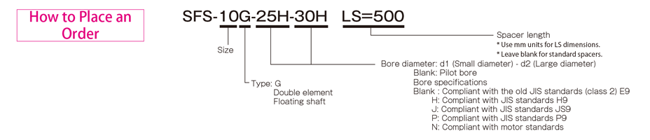
Types of SFS-□G
[Specifications]
| Model | Rated torque[N・m] | False | Max. rotation speed[min -1] | Torsional stiffness[N・m/rad] | Axial stiffness[N/mm] | Moment of inertia[kg・m 2] | Weight[kg] | ||
|---|---|---|---|---|---|---|---|---|---|
| Song song[mm] | Angle[°] | Shaft[mm] | |||||||
| SFS-05G | 20 | 0,5 | 1(One side) | ±1,2 | 20000 | 8000 | 21 | 0,20×10 -3 | 0,50 |
| SFS-06G | 40 | 0,5 | 1(One side) | ±1,6 | 16000 | 14000 | 22 | 0,55×10 -3 | 0,90 |
| SFS-08G | 80 | 0,5 | 1(One side) | ±2,0 | 13000 | 41000 | 30 | 1,50 × 10 -3 | 1,70 |
| SFS-09G | 180 | 0,6 | 1(One side) | ±2,4 | 12000 | 85000 | 61 | 2,90×10 -3 | 2,40 |
| SFS-10G | 250 | 0,6 | 1(One side) | ±2,8 | 10000 | 125000 | 80 | 4,60×10 -3 | 3h30 |
| SFS-12G | 450 | 0,8 | 1(One side) | ±3,2 | 8000 | 215000 | 98 | 11,80×10 -3 | 5,80 |
| SFS-14G | 800 | 0,9 | 1(One side) | ±3,6 | 7000 | 390000 | 156 | 21,20×10 -3 | 8:60 a.m |
*Max. Rotation speed does not take into account dynamic balance.
*Moment of inertia and mass measured for maximum bore diameter.
[Size]

| Model | d1・d2 | D | N | L | LF | LS | S | F | K | M | ||
|---|---|---|---|---|---|---|---|---|---|---|---|---|
| pilot drill hole | Minimum. | Max. | ||||||||||
| SFS-05G | 7 | 8 | 20 | 56 | 32 | 74 | 20 | 24 | 5 | 11 | 24 | 8-M5×22 |
| SFS-06G | 7 | 8 | 25 | 68 | 40 | 86 | 25 | 24 | 6 | 10 | 30 | 8-M6×25 |
| SFS-08G | 10 | 11 | 35 | 82 | 54 | 98 | 30 | 26 | 6 | 11 | 38 | 8-M6×29 |
| SFS-09G | 10 | 11 | 38 | 94 | 58 | 106 | 30 | 30 | 8 | 21 | 42 | 8-M8×36 |
| SFS-10G | 15 | 16 | 42 | 104 | 68 | 120 | 35 | 30 | 10 | 16 | 48 | 8-M8×36 |
| SFS-12G | 18 | 19 | 50 | 126 | 78 | 140 | 40 | 38 | 11 | 23 | 54 | 8-M10×45 |
| SFS-14G | 20 | 22 | 60 | 144 | 88 | 160 | 45 | 46 | 12 | 31 | 61 | 8-M12×54 |
* Pilot holes must be drilled into the part.
*If you require a product with LS dimensions exceeding the above dimensions, please contact Miki Pulley with your required dimensions [mm]. Please contact Miki Pulley for assistance if the LS size is smaller than that
* The nominal diameter of a bored bolt M is equal to the quantity minus the nominal diameter of the screw thread multiplied by the nominal length.
[Standard bore diameter]
| Model | Standard hole diameter d1・d2 [mm] | |||||||||||||||||||||||||||
|---|---|---|---|---|---|---|---|---|---|---|---|---|---|---|---|---|---|---|---|---|---|---|---|---|---|---|---|---|
| 8 | 9 | 10 | 11 | 12 | 14 | 15 | 16 | 17 | 18 | 19 | 20 | 22 | 24 | 25 | 28 | 30 | 32 | 35 | 38 | 40 | 42 | 45 | 48 | 50 | 55 | 56 | 60 | |
| SFS-05G | ● | ● | ● | ● | ● | ● | ● | ● | ● | ● | ● | ● | ||||||||||||||||
| SFS-06G | ● | ● | ● | ● | ● | ● | ● | ● | ● | ● | ● | ● | ● | ● | ● | |||||||||||||
| SFS-08G | ● | ● | ● | ● | ● | ● | ● | ● | ● | ● | ● | ● | ● | ● | ● | ● | ||||||||||||
| SFS-09G | ● | ● | ● | ● | ● | ● | ● | ● | ● | ● | ● | ● | ● | ● | ● | ● | ● | |||||||||||
| SFS-10G | ● | ● | ● | ● | ● | ● | ● | ● | ● | ● | ● | ● | ● | ● | ● | |||||||||||||
| SFS-12G | ● | ● | ● | ● | ● | ● | ● | ● | ● | ● | ● | ● | ● | ● | ● | |||||||||||||
| SFS-14G | ● | ● | ● | ● | ● | ● | ● | ● | ● | ● | ● | ● | ● | ● | ● | ● | ||||||||||||
* Hole diameters marked with ● are supported as standard hole diameters. See standard hole drilling standards for information.
[Standard hole drilling standards]
| Models comply with the old JIS standard (type 2) JIS B 1301 1959 | The models comply with the new JIS standard (H9) JIS B 1301 1996 | Models comply with the new JIS standard (JS9) JIS B 1301 1996 | ||||||||||||
|---|---|---|---|---|---|---|---|---|---|---|---|---|---|---|
| Nominal hole diameter | Bore diameter(d1・d2) | Keyway height(W1・W2) | Keyway height(T1・T2) | Set the screw hole(M | Nominal hole diameter | Bore diameter(d1・d2) | Keyway height(W1・W2) | Keyway height(T1・T2) | Set the screw hole(M | Nominal hole diameter | Bore diameter(d1・d2) | Keyway height(W1・W2) | Keyway height(T1・T2) | Set the screw hole(M |
| ToleranceH7,H8 | ToleranceE9 | - | - | ToleranceH7,H8 | ToleranceH9 | - | - | ToleranceH7,H8 | ToleranceJS9 | - | - | |||
| 8 | 8 +0,022 0 | - | - | 2-M4 | 8 O'CLOCK | 8 +0,022 0 | 3 +0,025 0 | 9,4 +0,3 0 | 2-M4 | 8J | 8 +0,022 0 | 3 ±0,0125 | 9,4 +0,3 0 | 2-M4 |
| 9 | 9 +0,022 0 | - | - | 2-M4 | 9H | 9 +0,022 0 | 3 +0,025 0 | 10,4 +0,3 0 | 2-M4 | 9J | 9 +0,022 0 | 3 ±0,0125 | 10,4 +0,3 0 | 2-M4 |
| 10 | 10 +0,022 0 | - | - | 2-M4 | 10H | 10 +0,022 0 | 3 +0,025 0 | 11,4 +0,3 0 | 2-M4 | 10J | 10 +0,022 0 | 3 ±0,0125 | 11,4 +0,3 0 | 2-M4 |
| 11 | 11 +0,018 0 | - | - | 2-M4 | 11H | 11 +0,018 0 | 4 +0,030 0 | 12,8 +0,3 0 | 2-M4 | 11J | 11 +0,018 0 | 4 ±0,0150 | 12,8 +0,3 0 | 2-M4 |
| 12 | 12 +0,018 0 | 4 +0,050 +0,020 | 13,5 +0,3 0 | 2-M4 | 12H | 12 +0,018 0 | 4 +0,030 0 | 13,8 +0,3 0 | 2-M4 | 12J | 12 +0,018 0 | 4 ±0,0150 | 13,8 +0,3 0 | 2-M4 |
| 14 | 14 +0,018 0 | 5 +0,050 +0,020 | 16 +0,3 0 | 2-M4 | 14H | 14 +0,018 0 | 5 +0,030 0 | 16,3 +0,3 0 | 2-M4 | 14Y | 14 +0,018 0 | 5 ±0,0150 | 16,3 +0,3 0 | 2-M4 |
| 15 | 15 +0,018 0 | 5 +0,050 +0,020 | 17 +0,3 0 | 2-M4 | 15H | 15 +0,018 0 | 5 +0,030 0 | 17,3 +0,3 0 | 2-M4 | 15J | 15 +0,018 0 | 5 ±0,0150 | 17,3 +0,3 0 | 2-M4 |
| 16 | 16 +0,018 0 | 5 +0,050 +0,020 | 18 +0,3 0 | 2-M4 | 16H | 16 +0,018 0 | 5 +0,030 0 | 18,3 +0,3 0 | 2-M4 | 16J | 16 +0,018 0 | 5 ±0,0150 | 18,3 +0,3 0 | 2-M4 |
| 17 | 17 +0,018 0 | 5 +0,050 +0,020 | 19 +0,3 0 | 2-M4 | 17H | 17 +0,018 0 | 5 +0,030 0 | 19,3 +0,3 0 | 2-M4 | 17J | 17 +0,018 0 | 5 ±0,0150 | 19,3 +0,3 0 | 2-M4 |
| 18 | 18 +0,018 0 | 5 +0,050 +0,020 | 20 +0,3 0 | 2-M4 | 18H | 18 +0,018 0 | 6 +0,030 0 | 20,8 +0,3 0 | 2-M5 | 18J | 18 +0,018 0 | 6 ±0,0150 | 20,8 +0,3 0 | 2-M5 |
| 19 | 19 +0,021 0 | 5 +0,050 +0,020 | 21 +0,3 0 | 2-M4 | 19H | 19 +0,021 0 | 6 +0,030 0 | 21,8 +0,3 0 | 2-M5 | 19J | 19 +0,021 0 | 6 ±0,0150 | 21,8 +0,3 0 | 2-M5 |
| 20 | 20 +0,021 0 | 5 +0,050 +0,020 | 22 +0,3 0 | 2-M4 | 20H | 20 +0,021 0 | 6 +0,030 0 | 22,8 +0,3 0 | 2-M5 | 20J | 20 +0,021 0 | 6 ±0,0150 | 22,8 +0,3 0 | 2-M5 |
| 22 | 22 +0,021 0 | 7 +0,061 +0,025 | 25 +0,3 0 | 2-M6 | 10 p.m | 22 +0,021 0 | 6 +0,030 0 | 24,8 +0,3 0 | 2-M5 | 22J | 22 +0,021 0 | 6 ±0,0150 | 24,8 +0,3 0 | 2-M5 |
| 24 | 24 +0,021 0 | 7 +0,061 +0,025 | 27 +0,3 0 | 2-M6 | 24H | 24 +0,021 0 | 8 +0,036 0 | 27,3 +0,3 0 | 2-M6 | 24J | 24 +0,021 0 | 8 ±0,0180 | 27,3 +0,3 0 | 2-M6 |
| 25 | 25 +0,021 0 | 7 +0,061 +0,025 | 28 +0,3 0 | 2-M6 | 25H | 25 +0,021 0 | 8 +0,036 0 | 28,3 +0,3 0 | 2-M6 | 25J | 25 +0,021 0 | 8 ±0,0180 | 28,3 +0,3 0 | 2-M6 |
| 28 | 28 +0,021 0 | 7 +0,061 +0,025 | 31 +0,3 0 | 2-M6 | 28 hours | 28 +0,021 0 | 8 +0,036 0 | 31,3 +0,3 0 | 2-M6 | 28J | 28 +0,021 0 | 8 ±0,0180 | 31,3 +0,3 0 | 2-M6 |
| 30 | 30 +0,021 0 | 7 +0,061 +0,025 | 33 +0,3 0 | 2-M6 | 30 hours | 30 +0,021 0 | 8 +0,036 0 | 33,3 +0,3 0 | 2-M6 | 30J | 30 +0,021 0 | 8 ±0,0180 | 33,3 +0,3 0 | 2-M6 |
| 32 | 32 +0,025 0 | 10 +0,061 +0,025 | 35,5 +0,3 0 | 2-M8 | 32H | 32 +0,025 0 | 10 +0,036 0 | 35,3 +0,3 0 | 2-M8 | 32J | 32 +0,025 0 | 10 ±0,0180 | 35,3 +0,3 0 | 2-M8 |
| 35 | 35 +0,025 0 | 10 +0,061 +0,025 | 38,5 +0,3 0 | 2-M8 | 35H | 35 +0,025 0 | 10 +0,036 0 | 38,3 +0,3 0 | 2-M8 | 35J | 35 +0,025 0 | 10 ±0,0180 | 38,3 +0,3 0 | 2-M8 |
| 38 | 38 +0,025 0 | 10 +0,061 +0,025 | 41,5 +0,3 0 | 2-M8 | 38H | 38 +0,025 0 | 10 +0,036 0 | 41,3 +0,3 0 | 2-M8 | 38J | 38 +0,025 0 | 10 ±0,0180 | 41,3 +0,3 0 | 2-M8 |
| 40 | 40 +0,025 0 | 10 +0,061 +0,025 | 43,5 +0,3 0 | 2-M8 | 40H | 40 +0,025 0 | 12 +0,043 0 | 43,3 +0,3 0 | 2-M8 | 40J | 40 +0,025 0 | 12 ±0,0215 | 43,3 +0,3 0 | 2-M8 |
| 42 | 42 +0,025 0 | 12 +0,075 +0,032 | 45,5 +0,3 0 | 2-M8 | 42H | 42 +0,025 0 | 12 +0,043 0 | 45,3 +0,3 0 | 2-M8 | 42J | 42 +0,025 0 | 12 ±0,0215 | 45,3 +0,3 0 | 2-M8 |
| 45 | 45 +0,025 0 | 12 +0,075 +0,032 | 48,5 +0,3 0 | 2-M8 | 45H | 45 +0,025 0 | 14 +0,043 0 | 48,8 +0,3 0 | 2-M10 | 45J | 45 +0,025 0 | 14 ±0,0215 | 48,8 +0,3 0 | 2-M10 |
| 48 | 48 +0,025 0 | 12 +0,075 +0,032 | 51,5 +0,3 0 | 2-M8 | 48H | 48 +0,025 0 | 14 +0,043 0 | 51,8 +0,3 0 | 2-M10 | 48J | 48 +0,025 0 | 14 ±0,0215 | 51,8 +0,3 0 | 2-M10 |
| 50 | 50 +0,025 0 | 12 +0,075 +0,032 | 53,5 +0,3 0 | 2-M8 | 50H | 50 +0,025 0 | 14 +0,043 0 | 53,8 +0,3 0 | 2-M10 | 50J | 50 +0,025 0 | 14 ±0,0215 | 53,8 +0,3 0 | 2-M10 |
| 55 | 55 +0,030 0 | 15 +0,075 +0,032 | 60 +0,3 0 | 2-M10 | 55H | 55 +0,030 0 | 16 +0,043 0 | 59,3 +0,3 0 | 2-M10 | 55J | 55 +0,030 0 | 16 ±0,0215 | 59,3 +0,3 0 | 2-M10 |
| 56 | 56 +0,030 0 | 15 +0,075 +0,032 | 61 +0,3 0 | 2-M10 | 56H | 56 +0,030 0 | 16 +0,043 0 | 60,3 +0,3 0 | 2-M10 | 56J | 56 +0,030 0 | 16 ±0,0215 | 60,3 +0,3 0 | 2-M10 |
| 60 | 60 +0,030 0 | 15 +0,075 +0,032 | 65 +0,3 0 | 2-M10 | 60H | 60 +0,030 0 | 18 +0,043 0 | 64,4 +0,3 0 | 2-M10 | 60J | 60 +0,030 0 | 18 ±0,0215 | 64,4 +0,3 0 | 2-M10 |
| The models comply with the new JIS standard (P9) JIS B 1301 1996 | Model conforms to JIS C 4210 2001 engine standard | ||||||||
|---|---|---|---|---|---|---|---|---|---|
| Nominal hole diameter | Bore diameter(d1・d2) | Keyway width(W1・W2) | Keyway height(T1・T2) | Set the screw hole(M | Nominal hole diameter | Bore diameter(d1・d2) | Keyway width(W1・W2) | Keyway height(T1・T2) | Set the screw hole(M |
| ToleranceH7,H8 | ToleranceP9 | + 0,30 0 | - | - | ToleranceG7,F7 | ToleranceH9 | - | ||
| 8P | 8 +0,022 | 3 -0,006 -0,031 | 9,4 +0,3 0 | 2-M4 | - | - | - | - | - |
| 9P | 9 +0,022 | 3 -0,006 -0,031 | 10,4 +0,3 0 | 2-M4 | - | - | - | - | - |
| 10P | 10 +0,022 | 3 -0,006 -0,031 | 11,4 +0,3 0 | 2-M4 | - | - | - | - | - |
| 11P | 11 +0,018 | 4 -0,042 -0,012 | 12,8 +0,3 0 | 2-M4 | - | - | - | - | - |
| 12P | 12 +0,018 | 4 -0,042 -0,012 | 13,8 +0,3 0 | 2-M4 | - | - | - | - | - |
| 14P | 14 +0,018 | 5 -0,042 -0,012 | 16,3 +0,3 0 | 2-M4 | 14N | 14 +0,024 +0,006 | 5 +0,030 | 16,3 +0,3 0 | 2-M4 |
| 15P | 15 +0,018 | 5 -0,042 -0,012 | 17,3 +0,3 0 | 2-M4 | - | - | - | - | - |
| 16P | 16 +0,018 | 5 -0,042 -0,012 | 18,3 +0,3 0 | 2-M4 | - | - | - | - | - |
| 17P | 17 +0,018 | 5 -0,042 -0,012 | 19,3 +0,3 0 | 2-M4 | - | - | - | - | - |
| 18P | 18 +0,018 | 6 -0,042 -0,012 | 20,8 +0,3 0 | 2-M5 | - | - | - | - | - |
| 19P | 19 +0,021 | 6 -0,042 -0,012 | 21,8 +0,3 0 | 2-M5 | 19N | 19 +0,028 +0,007 | 6 +0,030 | 21,8 +0,3 0 | 2-M5 |
| 20P | 20 +0,021 | 6 -0,042 -0,012 | 22,8 +0,3 0 | 2-M5 | - | - | - | - | - |
| 22P | 22 +0,021 | 6 -0,042 -0,012 | 24,8 +0,3 0 | 2-M5 | - | - | - | - | - |
| 24P | 24 +0,021 | 8 -0,051 -0,015 | 27,3 +0,3 0 | 2-M6 | 24N | 24 +0,028 +0,007 | 8 +0,036 | 27,3 +0,3 0 | 2-M6 |
| 25P | 25 +0,021 | 8 -0,051 -0,015 | 28,3 +0,3 0 | 2-M6 | - | - | - | - | - |
| 28P | 28 +0,021 | 8 -0,051 -0,015 | 31,3 +0,3 0 | 2-M6 | 28N | 28 +0,028 +0,007 | 8 +0,036 | 31,3 +0,3 0 | 2-M6 |
| 30P | 30 +0,021 | 8 -0,051 -0,015 | 33,3 +0,3 0 | 2-M6 | - | - | - | - | - |
| 32P | 32 +0,025 | 10 -0,051 -0,015 | 35,3 +0,3 0 | 2-M8 | - | - | - | ||
| 35P | 35 +0,025 | 10 -0,051 -0,015 | 38,3 +0,3 0 | 2-M8 | - | - | - | - | |
| 38P | 38 +0,025 | 10 -0,051 -0,015 | 41,3 +0,3 0 | 2-M8 | 38N | 38 +0,050 +0,025 | 10 +0,036 | 41,3 +0,3 0 | 2-M8 |
| 40P | 40 +0,025 | 12 -0,061 -0,018 | 43,3 +0,3 0 | 2-M8 | - | - | - | - | - |
| 42P | 42 +0,025 | 12 -0,061 -0,018 | 45,3 +0,3 0 | 2-M8 | 42N | 42 +0,050 +0,025 | 12 +0,043 | 45,3 +0,3 0 | 2-M8 |
| 45P | 45 +0,025 | 14 -0,061 -0,018 | 48,8 +0,3 0 | 2-M10 | - | - | - | - | - |
| 48 P | 48 +0,025 | 14 -0,061 -0,018 | 51,8 +0,3 0 | 2-M10 | 48N | 48 +0,050 +0,025 | 14 +0,043 | 51,8 +0,3 0 | 2-M10 |
| 50P | 50 +0,025 | 14 -0,061 -0,018 | 53,8 +0,3 0 | 2-M10 | - | - | - | - | - |
| 55P | 55 +0,030 | 16 -0,061 -0,018 | 59,3 +0,3 0 | 2-M10 | 55N | 55 +0,060 +0,030 | 16 +0,043 | 59,3 +0,3 0 | 2-M10 |
| 56P | 56 +0,030 | 16 -0,061 -0,018 | 60,3 +0,3 0 | 2-M10 | - | - | - | - | - |
| 60P | 60 +0,030 | 18 -0,061 -0,018 | 64,4 +0,3 0 | 2-M10 | 60N | 60 +0,060 +0,030 | 18 +0,043 | 64,4 +0,3 0 | 2-M10 |
※The positions of the set screw and the keyway are not on the same plane.
※Screw set is included in the product.
※Positioning accuracy when milling keyway is determined by sight.
※Contact Miki Pulley when keyway positioning accuracy is required for a specific flange shaft.
※Refer to the technical documentation at the end of this volume for standard dimensions for borehole drilling in addition to those stated here.
[Set screw position]
| Model | Distance from edge [mm] |
|---|---|
| SFS-05 | 7 |
| SFS-06 | 9 |
| SFS-08 | 10 |
| SFS-09 | 10 |
| SFS-10 | 12 |
| SFS-12 | 12 |
| SFS-14 | 15 |
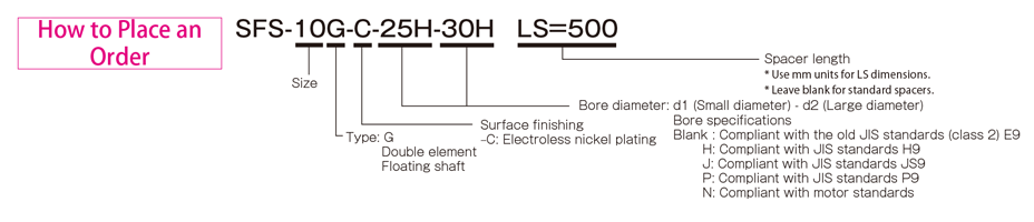
Types SFS-□G (C)
[Specifications]
[Size]
| Model | d1・d2 | D | N | L | LF | LS | S | F | K | M | ||
|---|---|---|---|---|---|---|---|---|---|---|---|---|
| pilot drill hole | Minimum. | Max. | ||||||||||
| SFS-05G-C | 7 | 8 | 20 | 56 | 32 | 74 | 20 | 24 | 5 | 11 | 24 | 8-M5×22 |
| SFS-06G-C | 7 | 8 | 25 | 68 | 40 | 86 | 25 | 24 | 6 | 10 | 30 | 8-M6×25 |
| SFS-08G-C | 10 | 11 | 35 | 82 | 54 | 98 | 30 | 26 | 6 | 11 | 38 | 8-M6×29 |
| SFS-09G-C | 10 | 11 | 38 | 94 | 58 | 106 | 30 | 30 | 8 | 21 | 42 | 8-M8×36 |
| SFS-10G-C | 15 | 16 | 42 | 104 | 68 | 120 | 35 | 30 | 10 | 16 | 48 | 8-M8×36 |
| SFS-12G-C | 18 | 19 | 50 | 126 | 78 | 140 | 40 | 38 | 11 | 23 | 54 | 8-M10×45 |
| SFS-14G-C | 20 | 22 | 60 | 144 | 88 | 160 | 45 | 46 | 12 | 31 | 61 | 8-M12×54 |
* If you require a product with LS dimensions exceeding the above dimensions, please contact Miki Pulley with your required dimensions [mm]. Please contact Miki Pulley for assistance if the LS size is smaller than the above size or if LS ≧ 1000.
* Please note that when the LS dimension exceeds 100 mm with electroless nickel plating (SFS- □ GC) specifications, the shaft insert length cannot exceed the LS dimension.
* The nominal diameter of a bored bolt M is equal to the quantity minus the nominal diameter of the screw thread multiplied by the nominal length.
[Standard bore diameter]
| Model | Standard hole diameter d1・d2 [mm] | |||||||||||||||||||||||||||
|---|---|---|---|---|---|---|---|---|---|---|---|---|---|---|---|---|---|---|---|---|---|---|---|---|---|---|---|---|
| 8 | 9 | 10 | 11 | 12 | 14 | 15 | 16 | 17 | 18 | 19 | 20 | 22 | 24 | 25 | 28 | 30 | 32 | 35 | 38 | 40 | 42 | 45 | 48 | 50 | 55 | 56 | 60 | |
| SFS-05G-C | ● | ● | ● | ● | ● | ● | ● | ● | ● | ● | ● | ● | ||||||||||||||||
| SFS-06G-C | ● | ● | ● | ● | ● | ● | ● | ● | ● | ● | ● | ● | ● | ● | ● | |||||||||||||
| SFS-08G-C | ● | ● | ● | ● | ● | ● | ● | ● | ● | ● | ● | ● | ● | ● | ● | ● | ||||||||||||
| SFS-09G-C | ● | ● | ● | ● | ● | ● | ● | ● | ● | ● | ● | ● | ● | ● | ● | ● | ● | |||||||||||
| SFS-10G-C | ● | ● | ● | ● | ● | ● | ● | ● | ● | ● | ● | ● | ● | ● | ● | |||||||||||||
| SFS-12G-C | ● | ● | ● | ● | ● | ● | ● | ● | ● | ● | ● | ● | ● | ● | ● | |||||||||||||
| SFS-14G-C | ● | ● | ● | ● | ● | ● | ● | ● | ● | ● | ● | ● | ● | ● | ● | ● | ||||||||||||
* Hole diameters marked with ● are supported as standard hole diameters. See standard hole drilling standards for information
[Standard hole drilling standards]
| Models comply with the old JIS standard (type 2) JIS B 1301 1959 | The models comply with the new JIS standard (H9) JIS B 1301 1996 | Models comply with the new JIS standard (JS9) JIS B 1301 1996 | ||||||||||||
|---|---|---|---|---|---|---|---|---|---|---|---|---|---|---|
| Nominal hole diameter | Bore diameter(d1・d2) | Keyway height(W1・W2) | Keyway height(T1・T2) | Set the screw hole(M | Nominal hole diameter | Bore diameter(d1・d2) | Keyway height(W1・W2) | Keyway height(T1・T2) | Set the screw hole(M | Nominal hole diameter | Bore diameter(d1・d2) | Keyway height(W1・W2) | Keyway height(T1・T2) | Set the screw hole(M |
| ToleranceH7,H8 | ToleranceE9 | - | - | ToleranceH7,H8 | ToleranceH9 | - | - | ToleranceH7,H8 | ToleranceJS9 | - | - | |||
| 8 | 8 +0,022 0 | - | - | 2-M4 | 8 O'CLOCK | 8 +0,022 0 | 3 +0,025 0 | 9,4 +0,3 0 | 2-M4 | 8J | 8 +0,022 0 | 3 ±0,0125 | 9,4 +0,3 0 | 2-M4 |
| 9 | 9 +0,022 0 | - | - | 2-M4 | 9H | 9 +0,022 0 | 3 +0,025 0 | 10,4 +0,3 0 | 2-M4 | 9J | 9 +0,022 0 | 3 ±0,0125 | 10,4 +0,3 0 | 2-M4 |
| 10 | 10 +0,022 0 | - | - | 2-M4 | 10H | 10 +0,022 0 | 3 +0,025 0 | 11,4 +0,3 0 | 2-M4 | 10J | 10 +0,022 0 | 3 ±0,0125 | 11,4 +0,3 0 | 2-M4 |
| 11 | 11 +0,018 0 | - | - | 2-M4 | 11H | 11 +0,018 0 | 4 +0,030 0 | 12,8 +0,3 0 | 2-M4 | 11J | 11 +0,018 0 | 4 ±0,0150 | 12,8 +0,3 0 | 2-M4 |
| 12 | 12 +0,018 0 | 4 +0,050 +0,020 | 13,5 +0,3 0 | 2-M4 | 12H | 12 +0,018 0 | 4 +0,030 0 | 13,8 +0,3 0 | 2-M4 | 12J | 12 +0,018 0 | 4 ±0,0150 | 13,8 +0,3 0 | 2-M4 |
| 14 | 14 +0,018 0 | 5 +0,050 +0,020 | 16 +0,3 0 | 2-M4 | 14H | 14 +0,018 0 | 5 +0,030 0 | 16,3 +0,3 0 | 2-M4 | 14Y | 14 +0,018 0 | 5 ±0,0150 | 16,3 +0,3 0 | 2-M4 |
| 15 | 15 +0,018 0 | 5 +0,050 +0,020 | 17 +0,3 0 | 2-M4 | 15H | 15 +0,018 0 | 5 +0,030 0 | 17,3 +0,3 0 | 2-M4 | 15J | 15 +0,018 0 | 5 ±0,0150 | 17,3 +0,3 0 | 2-M4 |
| 16 | 16 +0,018 0 | 5 +0,050 +0,020 | 18 +0,3 0 | 2-M4 | 16H | 16 +0,018 0 | 5 +0,030 0 | 18,3 +0,3 0 | 2-M4 | 16J | 16 +0,018 0 | 5 ±0,0150 | 18,3 +0,3 0 | 2-M4 |
| 17 | 17 +0,018 0 | 5 +0,050 +0,020 | 19 +0,3 0 | 2-M4 | 17H | 17 +0,018 0 | 5 +0,030 0 | 19,3 +0,3 0 | 2-M4 | 17J | 17 +0,018 0 | 5 ±0,0150 | 19,3 +0,3 0 | 2-M4 |
| 18 | 18 +0,018 0 | 5 +0,050 +0,020 | 20 +0,3 0 | 2-M4 | 18H | 18 +0,018 0 | 6 +0,030 0 | 20,8 +0,3 0 | 2-M5 | 18J | 18 +0,018 0 | 6 ±0,0150 | 20,8 +0,3 0 | 2-M5 |
| 19 | 19 +0,021 0 | 5 +0,050 +0,020 | 21 +0,3 0 | 2-M4 | 19H | 19 +0,021 0 | 6 +0,030 0 | 21,8 +0,3 0 | 2-M5 | 19J | 19 +0,021 0 | 6 ±0,0150 | 21,8 +0,3 0 | 2-M5 |
| 20 | 20 +0,021 0 | 5 +0,050 +0,020 | 22 +0,3 0 | 2-M4 | 20H | 20 +0,021 0 | 6 +0,030 0 | 22,8 +0,3 0 | 2-M5 | 20J | 20 +0,021 0 | 6 ±0,0150 | 22,8 +0,3 0 | 2-M5 |
| 22 | 22 +0,021 0 | 7 +0,061 +0,025 | 25 +0,3 0 | 2-M6 | 10 p.m | 22 +0,021 0 | 6 +0,030 0 | 24,8 +0,3 0 | 2-M5 | 22J | 22 +0,021 0 | 6 ±0,0150 | 24,8 +0,3 0 | 2-M5 |
| 24 | 24 +0,021 0 | 7 +0,061 +0,025 | 27 +0,3 0 | 2-M6 | 24H | 24 +0,021 0 | 8 +0,036 0 | 27,3 +0,3 0 | 2-M6 | 24J | 24 +0,021 0 | 8 ±0,0180 | 27,3 +0,3 0 | 2-M6 |
| 25 | 25 +0,021 0 | 7 +0,061 +0,025 | 28 +0,3 0 | 2-M6 | 25H | 25 +0,021 0 | 8 +0,036 0 | 28,3 +0,3 0 | 2-M6 | 25J | 25 +0,021 0 | 8 ±0,0180 | 28,3 +0,3 0 | 2-M6 |
| 28 | 28 +0,021 0 | 7 +0,061 +0,025 | 31 +0,3 0 | 2-M6 | 28 hours | 28 +0,021 0 | 8 +0,036 0 | 31,3 +0,3 0 | 2-M6 | 28J | 28 +0,021 0 | 8 ±0,0180 | 31,3 +0,3 0 | 2-M6 |
| 30 | 30 +0,021 0 | 7 +0,061 +0,025 | 33 +0,3 0 | 2-M6 | 30 hours | 30 +0,021 0 | 8 +0,036 0 | 33,3 +0,3 0 | 2-M6 | 30J | 30 +0,021 0 | 8 ±0,0180 | 33,3 +0,3 0 | 2-M6 |
| 32 | 32 +0,025 0 | 10 +0,061 +0,025 | 35,5 +0,3 0 | 2-M8 | 32H | 32 +0,025 0 | 10 +0,036 0 | 35,3 +0,3 0 | 2-M8 | 32J | 32 +0,025 0 | 10 ±0,0180 | 35,3 +0,3 0 | 2-M8 |
| 35 | 35 +0,025 0 | 10 +0,061 +0,025 | 38,5 +0,3 0 | 2-M8 | 35H | 35 +0,025 0 | 10 +0,036 0 | 38,3 +0,3 0 | 2-M8 | 35J | 35 +0,025 0 | 10 ±0,0180 | 38,3 +0,3 0 | 2-M8 |
| 38 | 38 +0,025 0 | 10 +0,061 +0,025 | 41,5 +0,3 0 | 2-M8 | 38H | 38 +0,025 0 | 10 +0,036 0 | 41,3 +0,3 0 | 2-M8 | 38J | 38 +0,025 0 | 10 ±0,0180 | 41,3 +0,3 0 | 2-M8 |
| 40 | 40 +0,025 0 | 10 +0,061 +0,025 | 43,5 +0,3 0 | 2-M8 | 40H | 40 +0,025 0 | 12 +0,043 0 | 43,3 +0,3 0 | 2-M8 | 40J | 40 +0,025 0 | 12 ±0,0215 | 43,3 +0,3 0 | 2-M8 |
| 42 | 42 +0,025 0 | 12 +0,075 +0,032 | 45,5 +0,3 0 | 2-M8 | 42H | 42 +0,025 0 | 12 +0,043 0 | 45,3 +0,3 0 | 2-M8 | 42J | 42 +0,025 0 | 12 ±0,0215 | 45,3 +0,3 0 | 2-M8 |
| 45 | 45 +0,025 0 | 12 +0,075 +0,032 | 48,5 +0,3 0 | 2-M8 | 45H | 45 +0,025 0 | 14 +0,043 0 | 48,8 +0,3 0 | 2-M10 | 45J | 45 +0,025 0 | 14 ±0,0215 | 48,8 +0,3 0 | 2-M10 |
| 48 | 48 +0,0250 | 12 +0,075 +0,032 | 51,5 +0,3 0 | 2-M8 | 48H | 48 +0,025 0 | 14 +0,043 0 | 51,8 +0,3 0 | 2-M10 | 48J | 48 +0,025 0 | 14 ±0,0215 | 51,8 +0,3 0 | 2-M10 |
| 50 | 50 +0,025 0 | 12 +0,075 +0,032 | 53,5 +0,3 0 | 2-M8 | 50H | 50 +0,025 0 | 14 +0,043 0 | 53,8 +0,3 0 | 2-M10 | 50J | 50 +0,025 0 | 14 ±0,0215 | 53,8 +0,3 0 | 2-M10 |
| 55 | 55 +0,030 0 | 15 +0,075 +0,032 | 60 +0,3 0 | 2-M10 | 55H | 55 +0,030 0 | 16 +0,043 0 | 59,3 +0,3 0 | 2-M10 | 55J | 55 +0,030 0 | 16 ±0,0215 | 59,3 +0,3 0 | 2-M10 |
| 56 | 56 +0,030 0 | 15 +0,075 +0,032 | 61 +0,3 0 | 2-M10 | 56H | 56 +0,030 0 | 16 +0,043 0 | 60,3 +0,3 0 | 2-M10 | 56J | 56 +0,030 0 | 16 ±0,0215 | 60,3 +0,3 0 | 2-M10 |
| 60 | 60 +0,030 0 | 15 +0,075 +0,032 | 65 +0,3 0 | 2-M10 | 60H | 60 +0,030 0 | 18 +0,043 0 | 64,4 +0,3 0 | 2-M10 | 60J | 60 +0,030 0 | 18 ±0,0215 | 64,4 +0,3 0 | 2-M10 |
| The models comply with the new JIS standard (P9) JIS B 1301 1996 | Model conforms to JIS C 4210 2001 engine standard | ||||||||
|---|---|---|---|---|---|---|---|---|---|
| Nominal hole diameter | Bore diameter(d1・d2) | Keyway width(W1・W2) | Keyway height(T1・T2) | Set the screw hole(M | Nominal hole diameter | Bore diameter(d1・d2) | Keyway width(W1・W2) | Keyway height(T1・T2) | Set the screw hole(M |
| ToleranceH7,H8 | ToleranceP9 | + 0,30 0 | - | - | ToleranceG7,F7 | ToleranceH9 | - | ||
| 8P | 8 +0,022 | 3 -0,006 -0,031 | 9,4 +0,3 0 | 2-M4 | - | - | - | - | - |
| 9P | 9 +0,022 | 3 -0,006 -0,031 | 10,4 +0,3 0 | 2-M4 | - | - | - | - | - |
| 10P | 10 +0,022 | 3 -0,006 -0,031 | 11,4 +0,3 0 | 2-M4 | - | - | - | - | - |
| 11P | 11 +0,018 | 4 -0,042 -0,012 | 12,8 +0,3 0 | 2-M4 | - | - | - | - | - |
| 12P | 12 +0,018 | 4 -0,042 -0,012 | 13,8 +0,3 0 | 2-M4 | - | - | - | - | - |
| 14P | 14 +0,018 | 5 -0,042 -0,012 | 16,3 +0,3 0 | 2-M4 | 14N | 14 +0,024 +0,006 | 5 +0,030 | 16,3 +0,3 0 | 2-M4 |
| 15P | 15 +0,018 | 5 -0,042 -0,012 | 17,3 +0,3 0 | 2-M4 | - | - | - | - | - |
| 16P | 16 +0,018 | 5 -0,042 -0,012 | 18,3 +0,3 0 | 2-M4 | - | - | - | - | - |
| 17P | 17 +0,018 | 5 -0,042 -0,012 | 19,3 +0,3 0 | 2-M4 | - | - | - | - | - |
| 18P | 18 +0,018 | 6 -0,042 -0,012 | 20,8 +0,3 0 | 2-M5 | - | - | - | - | - |
| 19P | 19 +0,021 | 6 -0,042 -0,012 | 21,8 +0,3 0 | 2-M5 | 19N | 19 +0,028 +0,007 | 6 +0,030 | 21,8 +0,3 0 | 2-M5 |
| 20P | 20 +0,021 | 6 -0,042 -0,012 | 22,8 +0,3 0 | 2-M5 | - | - | - | - | - |
| 22P | 22 +0,021 | 6 -0,042 -0,012 | 24,8 +0,3 0 | 2-M5 | - | - | - | - | - |
| 24P | 24 +0,021 | 8 -0,051 -0,015 | 27,3 +0,3 0 | 2-M6 | 24N | 24 +0,028 +0,007 | 8 +0,036 | 27,3 +0,3 0 | 2-M6 |
| 25P | 25 +0,021 | 8 -0,051 -0,015 | 28,3 +0,3 0 | 2-M6 | - | - | - | - | - |
| 28P | 28 +0,021 | 8 -0,051 -0,015 | 31,3 +0,3 0 | 2-M6 | 28N | 28 +0,028 +0,007 | 8 +0,036 | 31,3 +0,3 0 | 2-M6 |
| 30P | 30 +0,021 | 8 -0,051 -0,015 | 33,3 +0,3 0 | 2-M6 | - | - | - | - | - |
| 32P | 32 +0,025 | 10 -0,051 -0,015 | 35,3 +0,3 0 | 2-M8 | - | - | - | ||
| 35P | 35 +0,025 | 10 -0,051 -0,015 | 38,3 +0,3 0 | 2-M8 | - | - | - | - | |
| 38P | 38 +0,025 | 10 -0,051 -0,015 | 41,3 +0,3 0 | 2-M8 | 38N | 38 +0,050 +0,025 | 10 +0,036 | 41,3 +0,3 0 | 2-M8 |
| 40P | 40 +0,025 | 12 -0,061 -0,018 | 43,3 +0,3 0 | 2-M8 | - | - | - | - | - |
| 42P | 42 +0,025 | 12 -0,061 -0,018 | 45,3 +0,3 0 | 2-M8 | 42N | 42 +0,050 +0,025 | 12 +0,043 | 45,3 +0,3 0 | 2-M8 |
| 45P | 45 +0,025 | 14 -0,061 -0,018 | 48,8 +0,3 0 | 2-M10 | - | - | - | - | - |
| 48 P | 48 +0,025 | 14 -0,061 -0,018 | 51,8 +0,3 0 | 2-M10 | 48N | 48 +0,050 +0,025 | 14 +0,043 | 51,8 +0,3 0 | 2-M10 |
| 50P | 50 +0,025 | 14 -0,061 -0,018 | 53,8 +0,3 0 | 2-M10 | - | - | - | - | - |
| 55P | 55 +0,030 | 16 -0,061 -0,018 | 59,3 +0,3 0 | 2-M10 | 55N | 55 +0,060 +0,030 | 16 +0,043 | 59,3 +0,3 0 | 2-M10 |
| 56P | 56 +0,030 | 16 -0,061 -0,018 | 60,3 +0,3 0 | 2-M10 | - | - | - | - | - |
| 60P | 60 +0,030 | 18 -0,061 -0,018 | 64,4 +0,3 0 | 2-M10 | 60N | 60 +0,060 +0,030 | 18 +0,043 | 64,4 +0,3 0 | 2-M10 |
※The positions of the set screw and the keyway are not on the same plane.
※Screw set is included in the product.
※Positioning accuracy when milling keyway is determined by sight.
※Contact Miki Pulley when keyway positioning accuracy is required for a specific flange shaft.
※Refer to the technical documentation at the end of this volume for standard dimensions for borehole drilling in addition to those stated here.
[Set screw position]
| Model | Distance from edge [mm] |
|---|---|
| SFS-05 | 7 |
| SFS-06 | 9 |
| SFS-08 | 10 |
| SFS-09 | 10 |
| SFS-10 | 12 |
| SFS-12 | 12 |
| SFS-14 | 15 |
Related products
| CODE | NAME | NAME | BRAND |
| SFS-05S | Couplings SFS Models | Coupling the SFS model | Miki Pulley |
| SFS-06S | Couplings SFS Models | Coupling the SFS model | Miki Pulley |
| SFS-08S | Couplings SFS Models | Coupling the SFS model | Miki Pulley |
| SFS-09S | Couplings SFS Models | Coupling the SFS model | Miki Pulley |
| SFS-10S | Couplings SFS Models | Coupling the SFS model | Miki Pulley |
| SFS-12S | Couplings SFS Models | Coupling the SFS model | Miki Pulley |
| SFS-14S | Couplings SFS Models | Coupling the SFS model | Miki Pulley |
| SFS-05S-C | Couplings SFS Models | Coupling the SFS model | Miki Pulley |
| SFS-06S-C | Couplings SFS Models | Coupling the SFS model | Miki Pulley |
| SFS-08S-C | Couplings SFS Models | Coupling the SFS model | Miki Pulley |
| SFS-09S-C | Couplings SFS Models | Coupling the SFS model | Miki Pulley |
| SFS-10S-C | Couplings SFS Models | Coupling the SFS model | Miki Pulley |
| SFS-12S-C | Couplings SFS Models | Coupling the SFS model | Miki Pulley |
| SFS-14S-C | Couplings SFS Models | Coupling the SFS model | Miki Pulley |
| SFS-05W | Couplings SFS Models | Coupling the SFS model | Miki Pulley |
| SFS-06W | Couplings SFS Models | Coupling the SFS model | Miki Pulley |
| SFS-08W | Couplings SFS Models | Coupling the SFS model | Miki Pulley |
| SFS-09W | Couplings SFS Models | Coupling the SFS model | Miki Pulley |
| SFS-10W | Couplings SFS Models | Coupling the SFS model | Miki Pulley |
| SFS-12W | Couplings SFS Models | Coupling the SFS model | Miki Pulley |
| SFS-14W | Couplings SFS Models | Coupling the SFS model | Miki Pulley |
| SFS-05W-C | Couplings SFS Models | Coupling the SFS model | Miki Pulley |
| SFS-06W-C | Couplings SFS Models | Coupling the SFS model | Miki Pulley |
| SFS-08W-C | Couplings SFS Models | Coupling the SFS model | Miki Pulley |
| SFS-09W-C | Couplings SFS Models | Coupling the SFS model | Miki Pulley |
| SFS-10W-C | Couplings SFS Models | Coupling the SFS model | Miki Pulley |
| SFS-12W-C | Couplings SFS Models | Coupling the SFS model | Miki Pulley |
| SFS-14W-C | Couplings SFS Models | Coupling the SFS model | Miki Pulley |
| SFS-05G | Couplings SFS Models | Coupling the SFS model | Miki Pulley |
| SFS-06G | Couplings SFS Models | Coupling the SFS model | Miki Pulley |
| SFS-08G | Couplings SFS Models | Coupling the SFS model | Miki Pulley |
| SFS-09G | Couplings SFS Models | Coupling the SFS model | Miki Pulley |
| SFS-10G | Couplings SFS Models | Coupling the SFS model | Miki Pulley |
| SFS-12G | Couplings SFS Models | Coupling the SFS model | Miki Pulley |
| SFS-14G | Couplings SFS Models | Coupling the SFS model | Miki Pulley |
| SFS-05G-C | Couplings SFS Models | Coupling the SFS model | Miki Pulley |
| SFS-06G-C | Couplings SFS Models | Coupling the SFS model | Miki Pulley |
| SFS-08G-C | Couplings SFS Models | Coupling the SFS model | Miki Pulley |
| SFS-09G-C | Couplings SFS Models | Coupling the SFS model | Miki Pulley |
| SFS-10G-C | Couplings SFS Models | Coupling the SFS model | Miki Pulley |
| SFS-12G-C | Couplings SFS Models | Coupling the SFS model | Miki Pulley |
| SFS-14G-C | Couplings SFS Models | Coupling the SFS model | Miki Pulley |
See more technical documents here
See more technical products here
Link FaceBook Jon&Jul VietNam