CFA001O01360CFA Mikipulley Việt Nam
Price: Contact
Brand: Mikipulley Viet Nam
Category: Industrial joints
Supplier: Jon&Jul Việt Nam
Origin: Japan
Ứng dụng sản phẩm: accessory, Automation equipment, Electronic, Industry, Mechanical
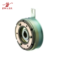
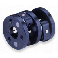
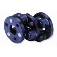
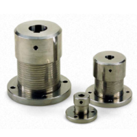
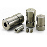
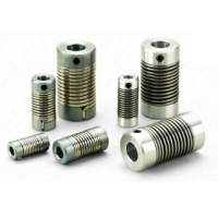
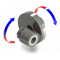
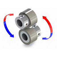
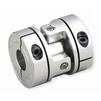
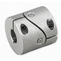
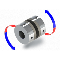
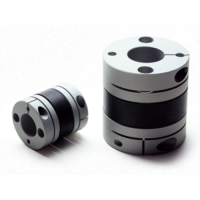
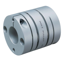
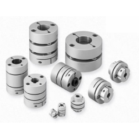
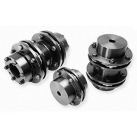
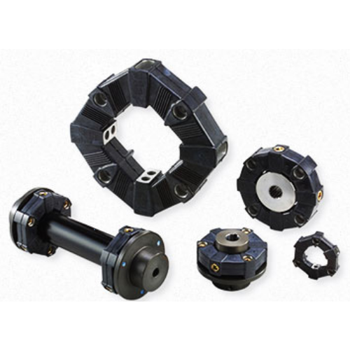
CFA001O01360CFA Models Pulley Pully Industrial coupling connector Mikipulley Vietnam
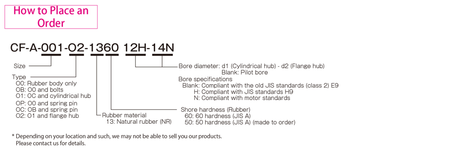
Introducing CFA001O01360CFA

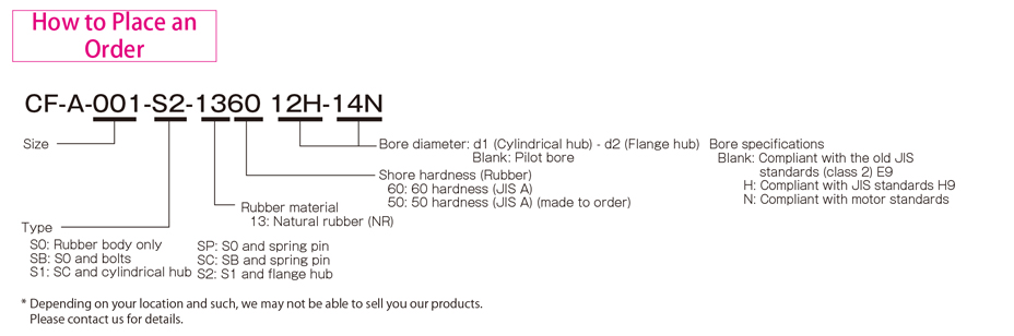
Types CF-A (O0/O1/O2)
[O0 specifications]
| Model | torque | False | Max. rotation speed [min -1] | Dynamic torsional stiffness [N・m/rad] | Moment of inertia [kg・m 2] | Weight[kg] | ||||
|---|---|---|---|---|---|---|---|---|---|---|
| Nominal [N・m] | Max. [N・m] | Continuous vibration torque [N・m/10Hz] | Song song [mm] | Angle [°] | Shaft [mm] | |||||
| CF-A-001-O0-1360 | 10 | 25 | ±4 | 0,5 | 3 | ±2 | 10000 | 1,47×10 2 | 2,5×10 -5 | 0,08 |
| CF-A-002-O0-1360 | 20 | 50 | ±8 | 1.0 | 3 | ±3 | 8000 | 2,92×10 2 | 1,3×10 -4 | 0,2 |
| CF-A-004-O0-1360 | 40 | 100 | ±16 | 1.0 | 3 | ±3 | 7000 | 7,59×10 2 | 2,8×10 -4 | 0,2 |
| CF-A-008-O0-1360 | 80 | 200 | ±32 | 1.0 | 3 | ±4 | 6500 | 1,44×10 3 | 7,6×10 -4 | 0,3 |
| CF-A-012-O0-1360 | 120 | 300 | ±48 | 1.0 | 2 | ±4 | 6500 | 4,38×10 3 | 8,3×10 -4 | 0,3 |
| CF-A-016-O0-1360 | 160 | 400 | ±64 | 1,5 | 3 | ±5 | 6000 | 3,28×10 3 | 2,5×10 -3 | 0,7 |
| CF-A-022-O0-1360 | 220 | 550 | ±88 | 1,5 | 2 | ±5 | 6000 | 8,26×10 3 | 2,7×10 -3 | 0,7 |
| CF-A-025-O0-1360 | 250 | 630 | ±100 | 1,5 | 3 | ±5 | 5000 | 4,12×10 3 | 4,2×10 -3 | 0,8 |
| CF-A-028-O0-1360 | 350 | 880 | ±140 | 1,5 | 2 | ±5 | 5000 | 1,05×10 4 | 4,6×10 -3 | 1.0 |
| CF-A-030-O0-1360 | 400 | 1000 | ±160 | 1,5 | 3 | ±5 | 4000 | 6,40×10 3 | 1,1×10 -2 | 1,5 |
| CF-A-050-O0-1360 | 600 | 1500 | ±240 | 1,5 | 2 | ±5 | 4000 | 1,48×10 4 | 1,2×10 -2 | 1.7 |
| CF-A-080-O0-1360 | 800 | 2000 | ±320 | 1,5 | 2 | ±4 | 4000 | 2,17×10 4 | 1,5×10 -2 | 2.3 |
| CF-A-090-O0-1360 | 900 | 2250 | ±360 | 1,5 | 3 | ±5 | 3600 | 1,37×10 4 | 3,8×10 -2 | 3.2 |
| CF-A-140-O0-1360 | 1400 | 3500 | ±560 | 1,5 | 2 | ±5 | 3600 | 2,90×10 4 | 4,2×10 -2 | 3,7 |
| CF-A-200-00-1360 | 2000 | 5000 | ±800 | 1,5 | 2 | ±5 | 3200 | 6,08×10 4 | 7,8×10 -2 | 5,5 |
| CF-A-250-O0-1360 | 3000 | 8750 | ±1250 | 1,5 | 2 | ±5 | 3000 | 8,28×10 4 | 0,14 | 7,8 |
| CF-A-400-00-1360 | 5000 | 12500 | ±2000 | 1,5 | 2 | ±5 | 2800 | 1,25×10 5 | 0,24 | 11,5 |
*Max. Rotation speed does not take into account dynamic balance.
* Dynamic torsional stiffness is about 1.3 times the static torsional stiffness.
*The moment of inertia and mass values are values when the cylindrical shaft and flange shaft have a pilot bore.
[O1 specifications]
| Model | torque | False | Max. rotation speed [min -1] | Dynamic torsional stiffness [N・m/rad] | Moment of inertia [kg・m 2] | Weight[kg] | ||||
|---|---|---|---|---|---|---|---|---|---|---|
| Nominal [N・m] | Max. [N・m] | Continuous vibration torque [N・m/10Hz] | Song song [mm] | Angle [°] | Shaft [mm] | |||||
| CF-A-001-O1-1360 | 10 | 25 | ±4 | 0,5 | 3 | ±2 | 10000 | 1,47×10 2 | 5,8×10 -5 | 0,3 |
| CF-A-002-O1-1360 | 20 | 50 | ±8 | 1.0 | 3 | ±3 | 8000 | 2,92×10 2 | 2,5×10 -4 | 0,5 |
| CF-A-004-O1-1360 | 40 | 100 | ±16 | 1.0 | 3 | ±3 | 7000 | 7,59×10 2 | 5,4×10 -4 | 0,6 |
| CF-A-008-O1-1360 | 80 | 200 | ±32 | 1.0 | 3 | ±4 | 6500 | 1,44×10 3 | 1,6×10 -3 | 1.3 |
| CF-A-012-O1-1360 | 120 | 300 | ±48 | 1.0 | 2 | ±4 | 6500 | 4,38×10 3 | 1,8×10 -3 | 1.3 |
| CF-A-016-O1-1360 | 160 | 400 | ±64 | 1,5 | 3 | ±5 | 6000 | 3,28×10 3 | 4,3×10 -3 | 2.3 |
| CF-A-022-O1-1360 | 220 | 550 | ±88 | 1,5 | 2 | ±5 | 6000 | 8,26×10 3 | 4,8×10 -3 | 2.4 |
| CF-A-025-O1-1360 | 250 | 630 | ±100 | 1,5 | 3 | ±5 | 5000 | 4,12×10 3 | 8,5×10 -3 | 3.6 |
| CF-A-028-O1-1360 | 350 | 880 | ±140 | 1,5 | 2 | ±5 | 5000 | 1,05×10 4 | 9,6×10 -3 | 3,8 |
| CF-A-030-O1-1360 | 400 | 1000 | ±160 | 1,5 | 3 | ±5 | 4000 | 6,40×10 3 | 2,1×10 -2 | 6.0 |
| CF-A-050-O1-1360 | 600 | 1500 | ±240 | 1,5 | 2 | ±5 | 4000 | 1,48×10 4 | 2,3×10 -2 | 6.3 |
| CF-A-080-O1-1360 | 800 | 2000 | ±320 | 1,5 | 2 | ±4 | 4000 | 2,17×10 4 | 2,6×10 -2 | 7,6 |
| CF-A-090-O1-1360 | 900 | 2250 | ±360 | 1,5 | 3 | ±5 | 3600 | 1,37×10 4 | 6,7×10 -2 | 11.8 |
| CF-A-140-O1-1360 | 1400 | 3500 | ±560 | 1,5 | 2 | ±5 | 3600 | 2,90×10 4 | 7,4×10 -2 | 12.6 |
| CF-A-200-O1-1360 | 2000 | 5000 | ±800 | 1,5 | 2 | ±5 | 3200 | 6,08×10 4 | 0,14 | 17,8 |
| CF-A-250-O1-1360 | 3000 | 8750 | ±1250 | 1,5 | 2 | ±5 | 3000 | 8,28×10 4 | 0,24 | 24,5 |
| CF-A-400-O1-1360 | 5000 | 12500 | ±2000 | 1,5 | 2 | ±5 | 2800 | 1,25×10 5 | 0,44 | 37,6 |
*Max. Rotation speed does not take into account dynamic balance.
* Dynamic torsional stiffness is about 1.3 times the static torsional stiffness.
*The moment of inertia and mass values are values when the cylindrical shaft and flange shaft have a pilot bore.
[O2 specifications]
| Model | torque | False | Max. rotation speed [min -1] | Dynamic torsional stiffness [N・m/rad] | Moment of inertia [kg・m 2] | Weight[kg] | ||||
|---|---|---|---|---|---|---|---|---|---|---|
| Nominal [N・m] | Max. [N・m] | Continuous vibration torque [N・m/10Hz] | Song song [mm] | Angle [°] | Shaft [mm] | |||||
| CF-A-001-O2-1360 | 10 | 25 | ±4 | 0,5 | 3 | ±2 | 10000 | 1,47×10² | 1,3×10 -4 | 0,5 |
| CF-A-002-O2-1360 | 20 | 50 | ±8 | 1.0 | 3 | ±3 | 8000 | 2,92×10² | 6,3×10 -4 | 1.1 |
| CF-A-004-O2-1360 | 40 | 100 | ±16 | 1.0 | 3 | ±3 | 7000 | 7,59×10² | 1,3×10 -3 | 1,5 |
| CF-A-008-O2-1360 | 80 | 200 | ±32 | 1.0 | 3 | ±4 | 6500 | 1,44×10³ | 3,7×10 -3 | 3.0 |
| CF-A-012-O2-1360 | 120 | 300 | ±48 | 1.0 | 2 | ±4 | 6500 | 4,38×10³ | 3,9×10 -3 | 3.1 |
| CF-A-016-O2-1360 | 160 | 400 | ±64 | 1,5 | 3 | ±5 | 6000 | 3,28×10³ | 1,1×10 -2 | 5,5 |
| CF-A-022-O2-1360 | 220 | 550 | ±88 | 1,5 | 2 | ±5 | 6000 | 8,26×10³ | 1,1×10 -2 | 5,6 |
| CF-A-025-O2-1360 | 250 | 630 | ±100 | 1,5 | 3 | ±5 | 5000 | 4,12×10³ | 2,1×10 -2 | 8,5 |
| CF-A-028-O2-1360 | 350 | 880 | ±140 | 1,5 | 2 | ±5 | 5000 | 1,05×10⁴ | 2,2×10 -2 | 8,7 |
| CF-A-030-O2-1360 | 400 | 1000 | ±160 | 1,5 | 3 | ±5 | 4000 | 6,40×10³ | 4,7×10 -2 | 13,8 |
| CF-A-050-O2-1360 | 600 | 1500 | ±240 | 1,5 | 2 | ±5 | 4000 | 1,48×10⁴ | 5,0×10 -2 | 14.2 |
| CF-A-080-O2-1360 | 800 | 2000 | ±320 | 1,5 | 2 | ±4 | 4000 | 2,17×10⁴ | 5,4×10 -2 | 15,5 |
| CF-A-090-O2-1360 | 900 | 2250 | ±360 | 1,5 | 3 | ±5 | 3600 | 1,37×10⁴ | 0,15 | 26.1 |
| CF-A-140-O2-1360 | 1400 | 3500 | ±560 | 1,5 | 2 | ±5 | 3600 | 2,90×10⁴ | 0,16 | 26,8 |
| CF-A-200-O2-1360 | 2000 | 5000 | ±800 | 1,5 | 2 | ±5 | 3200 | 6,08×10⁴ | 0,30 | 39,4 |
| CF-A-250-O2-1360 | 3000 | 8750 | ±1250 | 1,5 | 2 | ±5 | 3000 | 8,28×10⁴ | 0,50 | 52,3 |
| CF-A-400-O2-1360 | 5000 | 12500 | ±2000 | 1,5 | 2 | ±5 | 2800 | 1,25×10⁵ | 0,97 | 85,0 |
*Max. Rotation speed does not take into account dynamic balance.
* Dynamic torsional stiffness is about 1.3 times the static torsional stiffness.
*The moment of inertia and mass values are values when the cylindrical shaft and flange shaft have a pilot bore.
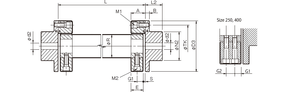
[Size]
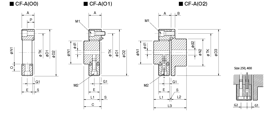
| Model | d1 | d2 | D1 | D2 | D3 | N1 | N2 | L1 | L2 | L3 | ONE | B | C | AND | G1 | G2 | Oh | P | S | TK | M1 | M2 | ||||
|---|---|---|---|---|---|---|---|---|---|---|---|---|---|---|---|---|---|---|---|---|---|---|---|---|---|---|
| pilot drill hole | Minimum. | Max. | pilot drill hole | Minimum. | Max. | |||||||||||||||||||||
| CF-A-001 | 8 | 9 | 19 | 8 | 9 | 22 | 57 | 56 | 56 | 30 | 36 | 32 | 24 | 58 | 24 | 7 | 34 | 22 | 11 | - | 5 | 18 | 2 | 44 | 2-M6 | 2-M6 |
| CF-A-002 | 10 | 11 | 28 | 9 | 10 | 30 | 86 | 85 | 85 | 40 | 45 | 30 | 28 | 62 | 24 | 8 | 34 | 20 | 10 | - | 14 | 12 | 4 | 68 | 2-M8 | 2-M8 |
| CF-A-004 | 12 | 14 | 30 | 11 | 12 | 36 | 100 | 97 | 100 | 45 | 55 | 34 | 30 | 68 | 28 | 8 | 38 | 24 | 12 | - | 18.3 | 17 | 4 | 80 | 3-M8 | 3-M8 |
| CF-A-008 | 12 | 14 | 38 | 15 | 16 | 46 | 122 | 120 | 120 | 60 | 70 | 40 | 42 | 86 | 32 | 10 | 44 | 28 | 14 | - | 20,5 | 20,5 | 4 | 100 | 3-M10 | 3-M10 |
| CF-A-012 | 12 | 14 | 38 | 15 | 16 | 46 | 122 | 120 | 120 | 60 | 70 | 40 | 42 | 86 | 32 | 10 | 44 | 28 | 14 | - | 20,5 | 20,5 | 4 | 100 | 4-M10 | 4-M10 |
| CF-A-016 | 15 | 16 | 48 | 19 | 20 | 56 | 150 | 150 | 150 | 70 | 85 | 52 | 50 | 108 | 42 | 12 | 58 | 36 | 18 | - | 25 | 23,5 | 6 | 125 | 3-M12 | 3-M12 |
| CF-A-022 | 15 | 16 | 48 | 19 | 20 | 56 | 150 | 150 | 150 | 70 | 85 | 52 | 50 | 108 | 42 | 12 | 58 | 36 | 18 | - | 25 | 23,5 | 6 | 125 | 4-M12 | 4-M12 |
| CF-A-025 | 15 | 16 | 55 | 19 | 20 | 65 | 170 | 170 | 170 | 85 | 100 | 58 | 56 | 120 | 46 | 14 | 64 | 40 | 20 | - | 26 | 26 | 6 | 140 | 3-M14 | 3-M14 |
| CF-A-028 | 15 | 16 | 55 | 19 | 20 | 65 | 170 | 170 | 170 | 85 | 100 | 58 | 56 | 120 | 46 | 14 | 64 | 40 | 20 | - | 26 | 26 | 6 | 140 | 4-M14 | 4-M14 |
| CF-A-030 | 20 | 22 | 65 | 28 | 30 | 80 | 200 | 200 | 200 | 100 | 120 | 68 | 66 | 142 | 58 | 16 | 76 | 50 | 25 | - | 33 | 34,5 | 8 | 165 | 3-M16 | 3-M16 |
| CF-A-050 | 20 | 22 | 65 | 28 | 30 | 80 | 200 | 200 | 200 | 100 | 120 | 68 | 66 | 142 | 58 | 16 | 76 | 50 | 25 | - | 33 | 34,5 | 8 | 165 | 4-M16 | 4-M16 |
| CF-A-080 | 20 | 22 | 65 | 28 | 30 | 80 | 205 | 205 | 200 | 100 | 120 | 80 | 66 | 150 | 65 | 16 | 84 | 61 | 30,5 | - | 33 | 34,5 | 4 | 165 | 4-M16 | 4-M16 |
| CF-A-090 | 30 | 32 | 85 | 30 | 32 | 95 | 260 | 260 | 260 | 125 | 140 | 84 | 80 | 172 | 70 | 19 | 92 | 62 | 31 | - | 46 | 45 | 8 | 215 | 3-M20 | 3-M20 |
| CF-A-140 | 30 | 32 | 85 | 30 | 32 | 95 | 260 | 260 | 260 | 125 | 140 | 84 | 80 | 172 | 70 | 19 | 92 | 62 | 31 | - | 46 | 45 | 8 | 215 | 4-M20 | 4-M20 |
| CF-A-200 | 35 | 38 | 105 | 35 | 38 | 110 | 300 | 300 | 300 | 145 | 160 | 94 | 90 | 192 | 80 | 19 | 102 | 72 | 36 | - | 46 | 45 | 8 | 250 | 4-M20 | 4-M20 |
| CF-A-250 | 40 | 42 | 115 | 40 | 42 | 120 | 340 | 340 | 340 | 160 | 180 | 100 | 100 | 208 | 85 | 19 | 108 | 77 | 22,5 | 32 | 60 | 60 | 8 | 280 | 4-M20 | 8-M20 |
| CF-A-400 | 40 | 42 | 115 | 40 | 42 | 130 | 370 | 370 | 370 | 170 | 200 | 125 | 125 | 260 | 105 | 29 | 135 | 95 | 28,5 | 38 | 70,5 | 67 | 10 | 300 | 4-M24 | 8-M20 |
* Pilot holes must be drilled into the part. The minimum value of d1 and d2 is calculated from the minimum bore diameter value in the MIKI PULLEY standard hole drilling standard and the maximum value from the maximum allowable bore diameter.
*The values in the table above are the dimensions when assembling the rubber body, so the N1, TK, D1 and D2 dimensions before assembling the rubber body will be different from the above dimensions.
*Dimension TK is the bolt pitch diameter of the flange shaft or mated assembly.
*The nominal diameter of M1/M2 bolts is the quantity minus the nominal diameter of the screw thread.
*Using hex head bolts with the CF-A-400 requires a special flat washer attached to the rubber shank.
[Standard hole drilling standards]

| Models comply with the old JIS standard (type 2) JIS B 1301 1959 |
The models comply with the new JIS standard (H9) JIS B 1301 1996 |
Model conforms to JIS C 4210 2001 engine standard |
||||||||||||
|---|---|---|---|---|---|---|---|---|---|---|---|---|---|---|
| Nominal hole diameter | Bore diameter (d1, d2) | Keyway width (W1, W2) | Keyway height (T1, T2) | Set screw hole (M) | Nominal hole diameter | Bore diameter (d1, d2) | Keyway width (W1, W2) | Keyway height (T1, T2) | Set screw hole (M) | Nominal hole diameter | Bore diameter (d1, d2) | Keyway width (W1, W2) | Keyway height (T1, T2) | Set screw hole (M) |
| Tolerance H7, H8 |
Tolerance E9 |
- | Tolerance H7 |
Tolerance H9 |
- | Tolerance G7, F7 |
Tolerance H9 |
- | ||||||
| 9 | 9 +0,022 0 | - | - | 2-M4 | - | - | - | - | - | - | - | - | - | - |
| 10 | 10 +0,022 0 | - | - | 2-M4 | - | - | - | - | - | - | - | - | - | - |
| 11 | 11 +0,018 0 | - | - | 2-M4 | - | - | - | - | - | - | - | - | - | - |
| 12 | 12 +0,018 0 | 4 +0,050 +0,020 | 13,5 +0,3 0 | 2-M4 | 12H | 12 +0,018 0 | 4 +0,030 0 | 13,8 +0,3 0 | 2-M4 | - | - | - | - | - |
| 14 | 14 +0,018 0 | 5 +0,050 +0,020 | 16,0 +0,3 0 | 2-M4 | 14H | 14 +0,018 0 | 5 +0,030 0 | 16,3 +0,3 0 | 2-M4 | 14N | 14 +0,024 +0,006 | 5 +0,030 0 | 16,3 +0,3 0 | 2-M4 |
| 15 | 15 +0,018 0 | 5 +0,050 +0,020 | 17,0 +0,3 0 | 2-M4 | 15H | 15 +0,018 0 | 5 +0,030 0 | 17,3 +0,3 0 | 2-M4 | - | - | - | - | - |
| 16 | 16 +0,018 0 | 5 +0,050 +0,020 | 18,0 +0,3 0 | 2-M4 | 16H | 16 +0,018 0 | 5 +0,030 0 | 18,3 +0,3 0 | 2-M4 | - | - | - | - | - |
| 17 | 17 +0,018 0 | 5 +0,050 +0,020 | 19,0 +0,3 0 | 2-M4 | 17H | 17 +0,018 0 | 5 +0,030 0 | 19,3 +0,3 0 | 2-M4 | - | - | - | - | - |
| 18 | 18 +0,018 0 | 5 +0,050 +0,020 | 20,0 +0,3 0 | 2-M4 | 18H | 18 +0,018 0 | 6 +0,030 0 | 20,8 +0,3 0 | 2-M5 | - | - | - | - | - |
| 19 | 19 +0,021 0 | 5 +0,050 +0,020 | 21,0 +0,3 0 | 2-M4 | 19H | 19 +0,021 0 | 6 +0,030 0 | 21,8 +0,3 0 | 2-M5 | 19N | 19 +0,028 +0,007 | 6 +0,030 0 | 21,8 +0,3 0 | 2-M5 |
| 20 | 20 +0,021 0 | 5 +0,050 +0,020 | 22,0 +0,3 0 | 2-M4 | 20H | 20 +0,021 0 | 6 +0,030 0 | 22,8 +0,3 0 | 2-M5 | - | - | - | - | - |
| 22 | 22 +0,021 0 | 7 +0,061 +0,025 | 25,0 +0,3 0 | 2-M6 | 10 p.m | 22 +0,021 0 | 6 +0,030 0 | 24,8 +0,3 0 | 2-M5 | - | - | - | - | - |
| 24 | 24 +0,021 0 | 7 +0,061 +0,025 | 27,0 +0,3 0 | 2-M6 | 24H | 24 +0,021 0 | 8 +0,036 0 | 27,3 +0,3 0 | 2-M6 | 24N | 24 +0,028 +0,007 | 8 +0,036 0 | 27,3 +0,3 0 | 2-M6 |
| 25 | 25 +0,0210 | 7 +0,061 +0,025 | 28,0 +0,3 0 | 2-M6 | 25H | 25 +0,021 0 | 8 +0,036 0 | 28,3 +0,3 0 | 2-M6 | - | - | - | - | - |
| 28 | 28 +0,021 0 | 7 +0,061 +0,025 | 31,0 +0,3 0 | 2-M6 | 28 hours | 28 +0,021 0 | 8 +0,036 0 | 31,3 +0,3 0 | 2-M6 | 28N | 28 +0,028 +0,007 | 8 +0,036 0 | 31,3 +0,3 0 | 2-M6 |
| 30 | 30 +0,021 0 | 7 +0,061 +0,025 | 33,0 +0,3 0 | 2-M6 | 30 hours | 30 +0,021 0 | 8 +0,036 0 | 33,3 +0,3 0 | 2-M6 | - | - | - | - | - |
| 32 | 32 +0,025 0 | 10 +0,061 +0,025 | 35,5 +0,3 0 | 2-M8 | 32H | 32 +0,025 0 | 10 +0,036 0 | 35,3 +0,3 0 | 2-M8 | - | - | - | - | - |
| 35 | 35 +0,025 0 | 10 +0,061 +0,025 | 38,5 +0,3 0 | 2-M8 | 35H | 35 +0,025 0 | 10 +0,036 0 | 38,3 +0,3 0 | 2-M8 | - | - | - | - | - |
| 38 | 38 +0,025 0 | 10 +0,061 +0,025 | 41,5 +0,3 0 | 2-M8 | 38H | 38 +0,025 0 | 10 +0,036 0 | 41,3 +0,3 0 | 2-M8 | 38N | 38 +0,050 +0,025 | 10 +0,036 0 | 41,3 +0,3 0 | 2-M8 |
| 40 | 40 +0,025 0 | 10 +0,061 +0,025 | 43,5 +0,3 0 | 2-M8 | 40H | 40 +0,025 0 | 12 +0,043 0 | 43,3 +0,3 0 | 2-M8 | - | - | - | - | - |
| 42 | 42 +0,025 0 | 12 +0,075 +0,032 | 45,5 +0,3 0 | 2-M8 | 42H | 42 +0,025 0 | 12 +0,043 0 | 45,3 +0,3 0 | 2-M8 | 42N | 42 +0,050 +0,025 | 12 +0,043 0 | 45,3 +0,3 0 | 2-M8 |
| 45 | 45 +0,025 0 | 12 +0,075 +0,032 | 48,5 +0,3 0 | 2-M8 | 45H | 45 +0,025 0 | 14 +0,043 0 | 48,8 +0,3 0 | 2-M10 | - | - | - | - | - |
| 48 | 48 +0,025 0 | 12 +0,075 +0,032 | 51,5 +0,3 0 | 2-M8 | 48H | 48 +0,025 0 | 14 +0,043 0 | 51,8 +0,3 0 | 2-M10 | 48N | 48 +0,050 +0,025 | 14 +0,043 0 | 51,8 +0,3 0 | 2-M10 |
| 50 | 50 +0,025 0 | 12 +0,075 +0,032 | 53,5 +0,3 0 | 2-M8 | 50H | 50 +0,025 0 | 14 +0,043 0 | 53,8 +0,3 0 | 2-M10 | - | - | - | - | - |
| 55 | 55 +0,030 0 | 15 +0,075 +0,032 | 60,0 +0,3 0 | 2-M10 | 55H | 55 +0,030 0 | 16 +0,043 0 | 59,3 +0,3 0 | 2-M10 | 55N | 55 +0,060 +0,030 | 16 +0,043 0 | 59,3 +0,3 0 | 2-M10 |
| 56 | 56 +0,030 0 | 15 +0,075 +0,032 | 61,0 +0,3 0 | 2-M10 | 56H | 56 +0,030 0 | 16 +0,043 0 | 60,3 +0,3 0 | 2-M10 | - | - | - | - | - |
| 60 | 60 +0,030 0 | 15 +0,075 +0,032 | 65,0 +0,3 0 | 2-M10 | 60H | 60 +0,030 0 | 18 +0,043 0 | 64,4 +0,3 0 | 2-M10 | 60N | 60 +0,060 +0,030 | 18 +0,043 0 | 64,4 +0,3 0 | 2-M10 |
| 63 | 63 +0,030 0 | 18 +0,075 +0,032 | 69,0 +0,3 0 | 2-M10 | 18H | 63 +0,030 0 | 18 +0,043 0 | 67,4 +0,3 0 | 2-M10 | - | - | - | - | - |
| 65 | 65 +0,030 0 | 18 +0,075 +0,032 | 71,0 +0,3 0 | 2-M10 | 65H | 65 +0,030 0 | 18 +0,043 0 | 69,4 +0,3 0 | 2-M10 | 65N | 65 +0,060 +0,030 | 18 +0,043 0 | 69,4 +0,3 0 | 2-M10 |
*All standards starting from ø11 are the same as those in the old JIS standards column.
*The positions of the set screw and keyway are not on the same plane.
*Screw set is included in the product.
*Positioning accuracy for keyway milling is determined by eye.
*Contact Miki Pulley when keyway positioning accuracy is required for a specific flange shaft.
*Refer to the technical documentation at the end of this volume for standard dimensions for bore drilling in addition to those given here.
*We can also machine shaft lines. Please contact Miki Pulley.
[Set Screw Position (Cylinder Shaft)]
Cylindrical center joint dimensions |
Distance from edge[mm] |
|---|---|
| 001 | 6 |
| 002・004 | 6 |
| 008・012 | 7 |
| 016・022・025・028 | 10 |
| 030・050・080 | 11 |
| 090・140 | 13 |
| 200・250・400 | 13 |
[Set Screw Position (Flange Shaft)]
| Flange center joint dimensions | Distance from edge[mm] |
|---|---|
| 001 | 6 |
| 002・004 | 7 |
| 008・012 | 9 |
| 016・022・025・028 | 10 |
| 030・050・080 | 15 |
| 090・140 | 15 |
| 200・250・400 | 16 |
Loại CF-A (S0/S1/S2)
[S0 Technical specifications]
| Model | torque | False | Max. rotation speed [min -1] | Dynamic torsional stiffness [N・m/rad] | Moment of inertia [kg・m 2] | Weight[kg] | ||||
|---|---|---|---|---|---|---|---|---|---|---|
| Nominal [N・m] | Max. [N・m] | Continuous vibration torque [N・m/10Hz] | Song song [mm] | Angle [°] | Shaft [mm] | |||||
| CF-A-001-S0-1360 | 10 | 25 | ±4 | 0,5 | 3 | ±2 | 10000 | 1,47×10 2 | 1,9×10 -5 | 0,07 |
| CF-A-002-S0-1360 | 20 | 50 | ±8 | 1.0 | 3 | ±3 | 8000 | 2,92×10 2 | 1,2×10 -4 | 0,1 |
| CF-A-004-S0-1360 | 40 | 100 | ±16 | 1.0 | 3 | ±3 | 7000 | 7,59×10 2 | 2,6×10 -4 | 0,2 |
| CF-A-008-S0-1360 | 80 | 200 | ±32 | 1.0 | 3 | ±4 | 6500 | 1,44×10 3 | 7,2×10 -4 | 0,3 |
| CF-A-012-S0-1360 | 120 | 300 | ±48 | 1.0 | 2 | ±4 | 6500 | 4,38×10 3 | 7,6×10 -4 | 0,3 |
| CF-A-016-S0-1360 | 160 | 400 | ±64 | 1,5 | 3 | ±5 | 6000 | 3,28×10 3 | 2,4×10 -3 | 0,6 |
| CF-A-022-S0-1360 | 220 | 550 | ±88 | 1,5 | 2 | ±5 | 6000 | 8,26×10 3 | 2,6×10 -3 | 0,7 |
| CF-A-025-S0-1360 | 250 | 630 | ±100 | 1,5 | 3 | ±5 | 5000 | 4,12×10 3 | 4,0×10 -3 | 0,8 |
| CF-A-028-S0-1360 | 350 | 880 | ±140 | 1,5 | 2 | ±5 | 5000 | 1,05×10 4 | 4,3×10 -3 | 0,9 |
| CF-A-030-S0-1360 | 400 | 1000 | ±160 | 1,5 | 3 | ±5 | 4000 | 6,40×10 3 | 1,0×10 -2 | 1.4 |
| CF-A-050-S0-1360 | 600 | 1500 | ±240 | 1,5 | 2 | ±5 | 4000 | 1,48×10 4 | 1,1×10 -2 | 1.7 |
| CF-A-080-S0-1360 | 800 | 2000 | ±320 | 1,5 | 2 | ±4 | 4000 | 2,17×10 4 | 1,5×10 -2 | 2.3 |
| CF-A-090-S0-1360 | 900 | 2250 | ±360 | 1,5 | 3 | ±5 | 3600 | 1,37×10 4 | 3,6×10 -2 | 3.1 |
| CF-A-140-S0-1360 | 1400 | 3500 | ±560 | 1,5 | 2 | ±5 | 3600 | 2,90×10 4 | 3,8×10 -2 | 3,4 |
| CF-A-200-S0-1360 | 2000 | 5000 | ±800 | 1,5 | 2 | ±5 | 3200 | 6,08×10 4 | 7,5×10 -2 | 5.3 |
| CF-A-250-S0-1360 | 3000 | 8750 | ±1250 | 1,5 | 2 | ±5 | 3000 | 8,28×10 4 | 0,14 | 7,0 |
| CF-A-400-S0-1360 | 5000 | 12500 | ±2000 | 1,5 | 2 | ±5 | 2800 | 1,25×10 5 | 0,22 | 10.7 |
*Max. Rotation speed does not take into account dynamic balance.
* Dynamic torsional stiffness is about 1.3 times the static torsional stiffness.
*The moment of inertia and mass values are values when the cylindrical shaft and flange shaft have a pilot bore
[S1 Specifications]
| Model | torque | False | Max. rotation speed [min -1] | Dynamic torsional stiffness [N・m/rad] | Moment of inertia [kg・m 2] | Weight[kg] | ||||
|---|---|---|---|---|---|---|---|---|---|---|
| Nominal [N・m] | Max. [N・m] | Continuous vibration torque [N・m/10Hz] | Song song [mm] | Angle [°] | Shaft [mm] | |||||
| CF-A-001-S1-1360 | 10 | 25 | ±4 | 0,5 | 3 | ±2 | 10000 | 1,47×10 2 | 6,0×10 -5 | 0,3 |
| CF-A-002-S1-1360 | 20 | 50 | ±8 | 1.0 | 3 | ±3 | 8000 | 2,92×10 2 | 2,8 × 10⁻⁴ | 0,5 |
| CF-A-004-S1-1360 | 40 | 100 | ±16 | 1.0 | 3 | ±3 | 7000 | 7,59×10 2 | 5,8×10 -4 | 0,7 |
| CF-A-008-S1-1360 | 80 | 200 | ±32 | 1.0 | 3 | ±4 | 6500 | 1,44×10 3 | 1,8×10 -3 | 1.4 |
| CF-A-012-S1-1360 | 120 | 300 | ±48 | 1.0 | 2 | ±4 | 6500 | 4,38×10 3 | 2,0×10 -3 | 1.4 |
| CF-A-016-S1-1360 | 160 | 400 | ±64 | 1,5 | 3 | ±5 | 6000 | 3,28×10 3 | 4,7×10 -3 | 2,5 |
| CF-A-022-S1-1360 | 220 | 550 | ±88 | 1,5 | 2 | ±5 | 6000 | 8,26×10 3 | 5,4×10 -3 | 2.6 |
| CF-A-025-S1-1360 | 250 | 630 | ±100 | 1,5 | 3 | ±5 | 5000 | 4,12×10 3 | 9,2×10 -3 | 3,8 |
| CF-A-028-S1-1360 | 350 | 880 | ±140 | 1,5 | 2 | ±5 | 5000 | 1,05×10 4 | 1,1×10 -3 | 4.0 |
| CF-A-030-S1-1360 | 400 | 1000 | ±160 | 1,5 | 3 | ±5 | 4000 | 6,40×10 3 | 2,2×10 -2 | 6.3 |
| CF-A-050-S1-1360 | 600 | 1500 | ±240 | 1,5 | 2 | ±5 | 4000 | 1,48×10 4 | 2,5×10 -2 | 6,8 |
| CF-A-080-S1-1360 | 800 | 2000 | ±320 | 1,5 | 2 | ±4 | 4000 | 2,17×10 4 | 2,9×10 -2 | 8.1 |
| CF-A-090-S1-1360 | 900 | 2250 | ±360 | 1,5 | 3 | ±5 | 3600 | 1,37×10 4 | 7,1×10 -2 | 12,4 |
| CF-A-140-S1-1360 | 1400 | 3500 | ±560 | 1,5 | 2 | ±5 | 3600 | 2,90×10 4 | 7,9×10 -2 | 13.3 |
| CF-A-200-S1-1360 | 2000 | 5000 | ±800 | 1,5 | 2 | ±5 | 3200 | 6,08×10 4 | 0,15 | 18,5 |
| CF-A-250-S1-1360 | 3000 | 8750 | ±1250 | 1,5 | 2 | ±5 | 3000 | 8,28×10 4 | 0,25 | 24,5 |
| CF-A-400-S1-1360 | 5000 | 12500 | ±2000 | 1,5 | 2 | ±5 | 2800 | 1,25×10 5 | 0,49 | 39,5 |
*Max. Rotation speed does not take into account dynamic balance.
* Dynamic torsional stiffness is about 1.3 times the static torsional stiffness.
*The moment of inertia and mass values are values when the cylindrical shaft and flange shaft have a pilot bore.
[S2 specifications]
| Model | torque | False | Max. rotation speed [min -1] | Dynamic torsional stiffness [N・m/rad] | Moment of inertia [kg・m 2] | Weight[kg] | ||||
|---|---|---|---|---|---|---|---|---|---|---|
| Nominal [N・m] | Max. [N・m] | Continuous vibration torque [N・m/10Hz] | Song song [mm] | Angle [°] | Shaft [mm] | |||||
| CF-A-001-S2-1360 | 10 | 25 | ±4 | 0,5 | 3 | ±2 | 10000 | 1,47×10 2 | 1,4×10⁻⁴ | 0,5 |
| CF-A-002-S2-1360 | 20 | 50 | ±8 | 1.0 | 3 | ±3 | 8000 | 2,92×10 2 | 6,6×10⁻⁴ | 1.1 |
| CF-A-004-S2-1360 | 40 | 100 | ±16 | 1.0 | 3 | ±3 | 7000 | 7,59×10 2 | 1,4×10⁻³ | 1,5 |
| CF-A-008-S2-1360 | 80 | 200 | ±32 | 1.0 | 3 | ±4 | 6500 | 1,44×10 3 | 3,9×10⁻³ | 3.1 |
| CF-A-012-S2-1360 | 120 | 300 | ±48 | 1.0 | 2 | ±4 | 6500 | 4,38×10 3 | 4,1×10⁻³ | 3.2 |
| CF-A-016-S2-1360 | 160 | 400 | ±64 | 1,5 | 3 | ±5 | 6000 | 3,28×10 3 | 1,1×10⁻² | 5,6 |
| CF-A-022-S2-1360 | 220 | 550 | ±88 | 1,5 | 2 | ±5 | 6000 | 8,26×10 3 | 1,2×10⁻² | 5,8 |
| CF-A-025-S2-1360 | 250 | 630 | ±100 | 1,5 | 3 | ±5 | 5000 | 4,12×10 3 | 2,2×10⁻² | 8,7 |
| CF-A-028-S2-1360 | 350 | 880 | ±140 | 1,5 | 2 | ±5 | 5000 | 1,05×10 4 | 2,3×10⁻² | 8,9 |
| CF-A-030-S2-1360 | 400 | 1000 | ±160 | 1,5 | 3 | ±5 | 4000 | 6,40×10 3 | 4,9×10⁻² | 14.2 |
| CF-A-050-S2-1360 | 600 | 1500 | ±240 | 1,5 | 2 | ±5 | 4000 | 1,48×10 4 | 5,2×10⁻² | 14.6 |
| CF-A-080-S2-1360 | 800 | 2000 | ±320 | 1,5 | 2 | ±4 | 4000 | 2,17×10 4 | 5,6×10⁻² | 16.0 |
| CF-A-090-S2-1360 | 900 | 2250 | ±360 | 1,5 | 3 | ±5 | 3600 | 1,37×10 4 | 0,16 | 26,6 |
| CF-A-140-S2-1360 | 1400 | 3500 | ±560 | 1,5 | 2 | ±5 | 3600 | 2,90×10 4 | 0,17 | 27,5 |
| CF-A-200-S2-1360 | 2000 | 5000 | ±800 | 1,5 | 2 | ±5 | 3200 | 6,08×10 4 | 0,32 | 40,1 |
| CF-A-250-S2-1360 | 3000 | 8750 | ±1250 | 1,5 | 2 | ±5 | 3000 | 8,28×10⁴ | 0,50 | 52,3 |
| CF-A-400-S2-1360 | 5000 | 12500 | ±2000 | 1,5 | 2 | ±5 | 2800 | 1,25×10⁵ | 1,00 | 86,9 |
*Max. Rotation speed does not take into account dynamic balance.
* Dynamic torsional stiffness is about 1.3 times the static torsional stiffness.
*The moment of inertia and mass values are values when the cylindrical shaft and flange shaft have a pilot bore.
[Size]
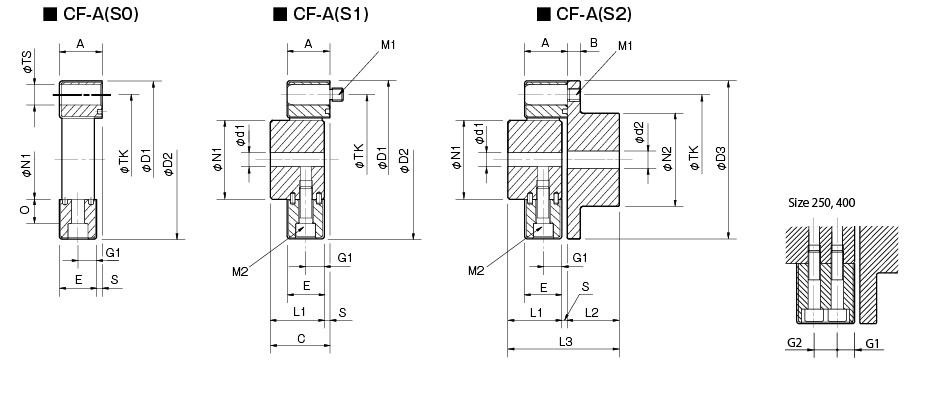
| Model | d1 | d2 | D1 | D2 | D3 | N1 | N2 | L1 | L2 | L3 | ONE | B | C | AND | G1 | G2 | Oh | S | TS | TK | M1 | M2 | ||||
|---|---|---|---|---|---|---|---|---|---|---|---|---|---|---|---|---|---|---|---|---|---|---|---|---|---|---|
| pilot drill hole | Minimum. | Max. | pilot drill hole | Minimum. | Max. | |||||||||||||||||||||
| CF-A-001 | 8 | 9 | 19 | 8 | 9 | 22 | 57 | 56 | 56 | 30 | 36 | 32 | 24 | 58 | 24 | 7 | 34 | 22 | 11 | - | 5 | 2 | 10 | 44 | 2-M6 | 2-M6 |
| CF-A-002 | 10 | 11 | 28 | 9 | 10 | 30 | 86 | 85 | 85 | 40 | 45 | 30 | 28 | 62 | 24 | 8 | 34 | 20 | 10 | - | 14 | 4 | 14 | 68 | 2-M8 | 2-M8 |
| CF-A-004 | 12 | 14 | 30 | 11 | 12 | 36 | 100 | 97 | 100 | 45 | 55 | 34 | 30 | 68 | 28 | 8 | 38 | 24 | 12 | - | 18.3 | 4 | 14 | 80 | 3-M8 | 3-M8 |
| CF-A-008 | 12 | 14 | 38 | 15 | 16 | 46 | 122 | 120 | 120 | 60 | 70 | 40 | 42 | 86 | 32 | 10 | 44 | 28 | 14 | - | 20,5 | 4 | 17 | 100 | 3-M10 | 3-M10 |
| CF-A-012 | 12 | 14 | 38 | 15 | 16 | 46 | 122 | 120 | 120 | 60 | 70 | 40 | 42 | 86 | 32 | 10 | 44 | 28 | 14 | - | 20,5 | 4 | 17 | 100 | 4-M10 | 4-M10 |
| CF-A-016 | 15 | 16 | 48 | 19 | 20 | 56 | 150 | 150 | 150 | 70 | 85 | 52 | 50 | 108 | 42 | 12 | 58 | 36 | 18 | - | 25 | 6 | 19 | 125 | 3-M12 | 3-M12 |
| CF-A-022 | 15 | 16 | 48 | 19 | 20 | 56 | 150 | 150 | 150 | 70 | 85 | 52 | 50 | 108 | 42 | 12 | 58 | 36 | 18 | - | 25 | 6 | 19 | 125 | 4-M12 | 4-M12 |
| CF-A-025 | 15 | 16 | 55 | 19 | 20 | 65 | 170 | 170 | 170 | 85 | 100 | 58 | 56 | 120 | 46 | 14 | 64 | 40 | 20 | - | 26 | 6 | 22 | 140 | 3-M14 | 3-M14 |
| CF-A-028 | 15 | 16 | 55 | 19 | 20 | 65 | 170 | 170 | 170 | 85 | 100 | 58 | 56 | 120 | 46 | 14 | 64 | 40 | 20 | - | 26 | 6 | 22 | 140 | 4-M14 | 4-M14 |
| CF-A-030 | 20 | 22 | 65 | 28 | 30 | 80 | 200 | 200 | 200 | 100 | 120 | 68 | 66 | 142 | 58 | 16 | 76 | 50 | 25 | - | 33 | 8 | 25 | 165 | 3-M16 | 3-M16 |
| CF-A-050 | 20 | 22 | 65 | 28 | 30 | 80 | 200 | 200 | 200 | 100 | 120 | 68 | 66 | 142 | 58 | 16 | 76 | 50 | 25 | - | 33 | 8 | 25 | 165 | 4-M16 | 4-M16 |
| CF-A-080 | 20 | 22 | 65 | 28 | 30 | 80 | 205 | 205 | 200 | 100 | 120 | 80 | 66 | 150 | 65 | 16 | 84 | 61 | 30,5 | - | 33 | 4 | 25 | 165 | 4-M16 | 4-M16 |
| CF-A-090 | 30 | 32 | 85 | 30 | 32 | 95 | 260 | 260 | 260 | 125 | 140 | 84 | 80 | 172 | 70 | 19 | 92 | 62 | 31 | - | 46 | 8 | 32 | 215 | 3-M20 | 3-M20 |
| CF-A-140 | 30 | 32 | 85 | 30 | 32 | 95 | 260 | 260 | 260 | 125 | 140 | 84 | 80 | 172 | 70 | 19 | 92 | 62 | 31 | - | 46 | 8 | 32 | 215 | 4-M20 | 4-M20 |
| CF-A-200 | 35 | 38 | 105 | 35 | 38 | 110 | 300 | 300 | 300 | 145 | 160 | 94 | 90 | 192 | 80 | 19 | 102 | 72 | 36 | - | 46 | 8 | 32 | 250 | 4-M20 | 4-M20 |
| CF-A-250 | 40 | 42 | 115 | 40 | 42 | 120 | 340 | 340 | 340 | 160 | 180 | 100 | 100 | 208 | 85 | 19 | 108 | 77 | 22,5 | 32 | 60 | 8 | 32 | 280 | 4-M20 | 8-M20 |
| CF-A-400 | 40 | 42 | 115 | 40 | 42 | 130 | 370 | 370 | 370 | 170 | 200 | 125 | 125 | 260 | 105 | 29 | 135 | 95 | 28,5 | 38 | 70,5 | 10 | 45 | 300 | 4-M24 | 8-M20 |
* Pilot holes must be drilled into the part. The minimum value of d1 and d2 is calculated from the minimum bore diameter value in the MIKI PULLEY standard hole drilling standard and the maximum value from the maximum allowable bore diameter.
*The values in the table above are the dimensions when assembling the rubber body, so the N1, TK, D1 and D2 dimensions before assembling the rubber body will be different from the above dimensions.
*Dimension TK is the bolt pitch diameter of the flange shaft or mated mounting member, but can be varied for easier mounting. Please contact MIKI PULLEY for more details.
*TS size is the reference size of the H8 plug gauge. However, size 001 has a tolerance of +0.1 0 , while sizes 002 and 004 have a tolerance of +0.15 0 .
*The nominal diameter of M1/M2 bolts is the quantity minus the nominal diameter of the screw thread.
*Using hex head bolts with the CF-A-400 requires a special flat washer attached to the rubber shank.
[Standard hole drilling standards]
| Models comply with the old JIS standard (type 2) JIS B 1301 1959 |
The models comply with the new JIS standard (H9) JIS B 1301 1996 |
Model conforms to JIS C 4210 2001 engine standard |
||||||||||||
|---|---|---|---|---|---|---|---|---|---|---|---|---|---|---|
| Nominal hole diameter | Bore diameter (d1, d2) | Keyway width (W1, W2) | Keyway height (T1, T2) | Set screw hole (M) | Nominal hole diameter | Bore diameter (d1, d2) | Keyway width (W1, W2) | Keyway height (T1, T2) | Set screw hole (M) | Nominal hole diameter | Bore diameter (d1, d2) | Keyway width (W1, W2) | Keyway height (T1, T2) | Set screw hole (M) |
| Tolerance H7, H8 |
Tolerance E9 |
- | Tolerance H7 |
Tolerance H9 |
- | Tolerance G7, F7 |
Tolerance H9 |
- | ||||||
| 9 | 9 +0,022 0 | - | - | 2-M4 | - | - | - | - | - | - | - | - | - | - |
| 10 | 10 +0,022 0 | - | - | 2-M4 | - | - | - | - | - | - | - | - | - | - |
| 11 | 11 +0,018 0 | - | - | 2-M4 | - | - | - | - | - | - | - | - | - | - |
| 12 | 12 +0,018 0 | 4 +0,050 +0,020 | 13,5 +0,3 0 | 2-M4 | 12H | 12 +0,018 0 | 4 +0,030 0 | 13,8 +0,3 0 | 2-M4 | - | - | - | - | - |
| 14 | 14 +0,018 0 | 5 +0,050 +0,020 | 16,0 +0,3 0 | 2-M4 | 14H | 14 +0,018 0 | 5 +0,030 0 | 16,3 +0,3 0 | 2-M4 | 14N | 14 +0,024 +0,006 | 5 +0,030 0 | 16,3 +0,3 0 | 2-M4 |
| 15 | 15 +0,018 0 | 5 +0,050 +0,020 | 17,0 +0,3 0 | 2-M4 | 15H | 15 +0,018 0 | 5 +0,030 0 | 17,3 +0,3 0 | 2-M4 | - | - | - | - | - |
| 16 | 16 +0,018 0 | 5 +0,050 +0,020 | 18,0 +0,3 0 | 2-M4 | 16H | 16 +0,018 0 | 5 +0,030 0 | 18,3 +0,3 0 | 2-M4 | - | - | - | - | - |
| 17 | 17 +0,018 0 | 5 +0,050 +0,020 | 19,0 +0,3 0 | 2-M4 | 17H | 17 +0,018 0 | 5 +0,030 0 | 19,3 +0,3 0 | 2-M4 | - | - | - | - | - |
| 18 | 18 +0,018 0 | 5 +0,050 +0,020 | 20,0 +0,3 0 | 2-M4 | 18H | 18 +0,018 0 | 6 +0,030 0 | 20,8 +0,3 0 | 2-M5 | - | - | - | - | - |
| 19 | 19 +0,021 0 | 5 +0,050 +0,020 | 21,0 +0,3 0 | 2-M4 | 19H | 19 +0,021 0 | 6 +0,030 0 | 21,8 +0,3 0 | 2-M5 | 19N | 19 +0,028 +0,007 | 6 +0,030 0 | 21,8 +0,3 0 | 2-M5 |
| 20 | 20 +0,0210 | 5 +0,050 +0,020 | 22,0 +0,3 0 | 2-M4 | 20H | 20 +0,021 0 | 6 +0,030 0 | 22,8 +0,3 0 | 2-M5 | - | - | - | - | - |
| 22 | 22 +0,021 0 | 7 +0,061 +0,025 | 25,0 +0,3 0 | 2-M6 | 10 p.m | 22 +0,021 0 | 6 +0,030 0 | 24,8 +0,3 0 | 2-M5 | - | - | - | - | - |
| 24 | 24 +0,021 0 | 7 +0,061 +0,025 | 27,0 +0,3 0 | 2-M6 | 24H | 24 +0,021 0 | 8 +0,036 0 | 27,3 +0,3 0 | 2-M6 | 24N | 24 +0,028 +0,007 | 8 +0,036 0 | 27,3 +0,3 0 | 2-M6 |
| 25 | 25 +0,021 0 | 7 +0,061 +0,025 | 28,0 +0,3 0 | 2-M6 | 25H | 25 +0,021 0 | 8 +0,036 0 | 28,3 +0,3 0 | 2-M6 | - | - | - | - | - |
| 28 | 28 +0,021 0 | 7 +0,061 +0,025 | 31,0 +0,3 0 | 2-M6 | 28 hours | 28 +0,021 0 | 8 +0,036 0 | 31,3 +0,3 0 | 2-M6 | 28N | 28 +0,028 +0,007 | 8 +0,036 0 | 31,3 +0,3 0 | 2-M6 |
| 30 | 30 +0,021 0 | 7 +0,061 +0,025 | 33,0 +0,3 0 | 2-M6 | 30 hours | 30 +0,021 0 | 8 +0,036 0 | 33,3 +0,3 0 | 2-M6 | - | - | - | - | - |
| 32 | 32 +0,025 0 | 10 +0,061 +0,025 | 35,5 +0,3 0 | 2-M8 | 32H | 32 +0,025 0 | 10 +0,036 0 | 35,3 +0,3 0 | 2-M8 | - | - | - | - | - |
| 35 | 35 +0,025 0 | 10 +0,061 +0,025 | 38,5 +0,3 0 | 2-M8 | 35H | 35 +0,025 0 | 10 +0,036 0 | 38,3 +0,3 0 | 2-M8 | - | - | - | - | - |
| 38 | 38 +0,025 0 | 10 +0,061 +0,025 | 41,5 +0,3 0 | 2-M8 | 38H | 38 +0,025 0 | 10 +0,036 0 | 41,3 +0,3 0 | 2-M8 | 38N | 38 +0,050 +0,025 | 10 +0,036 0 | 41,3 +0,3 0 | 2-M8 |
| 40 | 40 +0,025 0 | 10 +0,061 +0,025 | 43,5 +0,3 0 | 2-M8 | 40H | 40 +0,025 0 | 12 +0,043 0 | 43,3 +0,3 0 | 2-M8 | - | - | - | - | - |
| 42 | 42 +0,025 0 | 12 +0,075 +0,032 | 45,5 +0,3 0 | 2-M8 | 42H | 42 +0,025 0 | 12 +0,043 0 | 45,3 +0,3 0 | 2-M8 | 42N | 42 +0,050 +0,025 | 12 +0,043 0 | 45,3 +0,3 0 | 2-M8 |
| 45 | 45 +0,025 0 | 12 +0,075 +0,032 | 48,5 +0,3 0 | 2-M8 | 45H | 45 +0,025 0 | 14 +0,043 0 | 48,8 +0,3 0 | 2-M10 | - | - | - | - | - |
| 48 | 48 +0,025 0 | 12 +0,075 +0,032 | 51,5 +0,3 0 | 2-M8 | 48H | 48 +0,025 0 | 14 +0,043 0 | 51,8 +0,3 0 | 2-M10 | 48N | 48 +0,050 +0,025 | 14 +0,043 0 | 51,8 +0,3 0 | 2-M10 |
| 50 | 50 +0,025 0 | 12 +0,075 +0,032 | 53,5 +0,3 0 | 2-M8 | 50H | 50 +0,025 0 | 14 +0,043 0 | 53,8 +0,3 0 | 2-M10 | - | - | - | - | - |
| 55 | 55 +0,030 0 | 15 +0,075 +0,032 | 60,0 +0,3 0 | 2-M10 | 55H | 55 +0,030 0 | 16 +0,043 0 | 59,3 +0,3 0 | 2-M10 | 55N | 55 +0,060 +0,030 | 16 +0,043 0 | 59,3 +0,3 0 | 2-M10 |
| 56 | 56 +0,030 0 | 15 +0,075 +0,032 | 61,0 +0,3 0 | 2-M10 | 56H | 56 +0,030 0 | 16 +0,043 0 | 60,3 +0,3 0 | 2-M10 | - | - | - | - | - |
| 60 | 60 +0,030 0 | 15 +0,075 +0,032 | 65,0 +0,3 0 | 2-M10 | 60H | 60 +0,030 0 | 18 +0,0430 | 64,4 +0,3 0 | 2-M10 | 60N | 60 +0,060 +0,030 | 18 +0,043 0 | 64,4 +0,3 0 | 2-M10 |
| 63 | 63 +0,030 0 | 18 +0,075 +0,032 | 69,0 +0,3 0 | 2-M10 | 18H | 63 +0,030 0 | 18 +0,043 0 | 67,4 +0,3 0 | 2-M10 | - | - | - | - | - |
| 65 | 65 +0,030 0 | 18 +0,075 +0,032 | 71,0 +0,3 0 | 2-M10 | 65H | 65 +0,030 0 | 18 +0,043 0 | 69,4 +0,3 0 | 2-M10 | 65N | 65 +0,060 +0,030 | 18 +0,043 0 | 69,4 +0,3 0 | 2-M10 |
*All standards starting from ø11 are the same as those in the old JIS standards column.
*The positions of the set screw and keyway are not on the same plane.
*Screw set is included in the product.
*Positioning accuracy for keyway milling is determined by eye.
*Contact Miki Pulley when keyway positioning accuracy is required for a specific flange shaft.
*Refer to the technical documentation at the end of this volume for standard dimensions for bore drilling in addition to those given here.
*We can also machine shaft lines. Please contact Miki Pulley.
[Set Screw Position (Cylinder Shaft)]
Cylindrical center joint dimensions |
Distance from edge[mm] |
|---|---|
| 001 | 6 |
| 002・004 | 6 |
| 008・012 | 7 |
| 016・022・025・028 | 10 |
| 030・050・080 | 11 |
| 090・140 | 13 |
| 200・250・400 | 13 |
[Set Screw Position (Flange Shaft)]
| Flange center joint dimensions | Distance from edge[mm] |
|---|---|
| 001 | 6 |
| 002・004 | 7 |
| 008・012 | 9 |
| 016・022・025・028 | 10 |
| 030・050・080 | 15 |
| 090・140 | 15 |
| 200・250・400 | 16 |
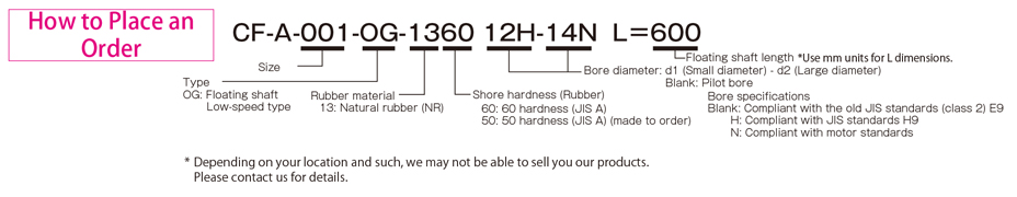
Types of CF-A (OG)
[Specifications]
| Model | torque | False | Max. rotation speed [min -1] | Dynamic torsional stiffness [N・m/rad] | Moment of inertia [kg・m 2] | Weight[kg] | ||||
|---|---|---|---|---|---|---|---|---|---|---|
| Nominal [N・m] | Max. [N・m] | Continuous vibration torque [N・m/10Hz] | Song song [mm] | Angle [°] | Shaft [mm] | |||||
| CF-A-001-OG-1360 | 10 | 25 | ±4 | 24.8 | 3 | ±2 | 1000 | 7,35×10 1 | 3,5×10 -4 | 1.4 |
| CF-A-002-OG-1360 | 20 | 50 | ±8 | 24,7 | 3 | ±3 | 1000 | 1,46×10 2 | 1,5×10 -3 | 2,5 |
| CF-A-004-OG-1360 | 40 | 100 | ±16 | 24,5 | 3 | ±3 | 1000 | 3,80×10 2 | 2,9×10 -3 | 3.3 |
| CF-A-008-OG-1360 | 80 | 200 | ±32 | 24.3 | 3 | ±4 | 1000 | 7,20×10 2 | 8,0×10 -3 | 6.2 |
| CF-A-012-OG-1360 | 120 | 300 | ±48 | 16.2 | 2 | ±4 | 1000 | 2,19×10 3 | 8,4×10 -3 | 6,4 |
| CF-A-016-OG-1360 | 160 | 400 | ±64 | 23,7 | 3 | ±5 | 1000 | 1,64×10 3 | 2,1×10 -2 | 10.6 |
| CF-A-022-OG-1360 | 220 | 550 | ±88 | 15,8 | 2 | ±5 | 1000 | 4,13×10 3 | 2,3×10 -2 | 11.0 |
| CF-A-025-OG-1360 | 250 | 630 | ±100 | 23,5 | 3 | ±5 | 1000 | 2,06×10 3 | 4,2×10 -2 | 15,9 |
| CF-A-028-OG-1360 | 350 | 880 | ±140 | 15,6 | 2 | ±5 | 1000 | 0,53×10 4 | 4,4×10 -2 | 16,5 |
| CF-A-030-OG-1360 | 400 | 1000 | ±160 | 22,7 | 3 | ±5 | 1000 | 3,20×10 3 | 9,6×10 -2 | 25,8 |
| CF-A-050-OG-1360 | 600 | 1500 | ±240 | 15.2 | 2 | ±5 | 1000 | 7,40×10 3 | 0,10 | 26,6 |
| CF-A-080-OG-1360 | 800 | 2000 | ±320 | 15.1 | 2 | ±4 | 1000 | 1,09×10 4 | 0,11 | 28,7 |
| CF-A-090-OG-1360 | 900 | 2250 | ±360 | 22.1 | 3 | ±5 | 1000 | 6,85×10 3 | 0,30 | 47,8 |
| CF-A-140-OG-1360 | 1400 | 3500 | ±560 | 14,7 | 2 | ±5 | 1000 | 1,45×10 4 | 0,31 | 49,3 |
| CF-A-200-OG-1360 | 2000 | 5000 | ±800 | 14.4 | 2 | ±5 | 1000 | 3,04×10 4 | 0,55 | 74,3 |
| CF-A-250-OG-1360 | 3000 | 8750 | ±1250 | 14.2 | 2 | ±5 | 1000 | 4,14×10 4 | 0,99 | 97,7 |
| CF-A-400-OG-1360 | 5000 | 12500 | ±2000 | 13,4 | 2 | ±5 | 1000 | 6,25×10 4 | 1,77 | 164,6 |
*The values in the table above are for flange hubs with pilot holes when L = 500.
*Max. Rotation speed does not take into account dynamic balance.
* Dynamic torsional stiffness is about 1.3 times the static torsional stiffness.
[Size]
| Model | d2 | D3 | N2 | L2 | ONE | B | R | AND | G1 | G2 | S | TK | M1 | M2 | ||
|---|---|---|---|---|---|---|---|---|---|---|---|---|---|---|---|---|
| pilot drill hole | Minimum. | Max. | ||||||||||||||
| CF-A-001-OG-1360 | 8 | 9 | 22 | 56 | 36 | 24 | 24 | 7 | 30 | 22 | 11 | - | 2 | 44 | 2-M6 | 2-M6 |
| CF-A-002-OG-1360 | 9 | 10 | 30 | 85 | 45 | 28 | 24 | 8 | 40 | 20 | 10 | - | 4 | 68 | 2-M8 | 2-M8 |
| CF-A-004-OG-1360 | 11 | 12 | 36 | 100 | 55 | 30 | 28 | 8 | 45 | 24 | 12 | - | 4 | 80 | 3-M8 | 3-M8 |
| CF-A-008-OG-1360 | 15 | 16 | 46 | 120 | 70 | 42 | 32 | 10 | 60 | 28 | 14 | - | 4 | 100 | 3-M10 | 3-M10 |
| CF-A-012-OG-1360 | 15 | 16 | 46 | 120 | 70 | 42 | 32 | 10 | 60 | 28 | 14 | - | 4 | 100 | 4-M10 | 4-M10 |
| CF-A-016-OG-1360 | 19 | 20 | 56 | 150 | 85 | 50 | 42 | 12 | 70 | 36 | 18 | - | 6 | 125 | 3-M12 | 3-M12 |
| CF-A-022-OG-1360 | 19 | 20 | 56 | 150 | 85 | 50 | 42 | 12 | 70 | 36 | 18 | - | 6 | 125 | 4-M12 | 4-M12 |
| CF-A-025-OG-1360 | 19 | 20 | 65 | 170 | 100 | 56 | 46 | 14 | 85 | 40 | 20 | - | 6 | 140 | 3-M14 | 3-M14 |
| CF-A-028-OG-1360 | 19 | 20 | 65 | 170 | 100 | 56 | 46 | 14 | 85 | 40 | 20 | - | 6 | 140 | 4-M14 | 4-M14 |
| CF-A-030-OG-1360 | 28 | 30 | 80 | 200 | 120 | 66 | 58 | 16 | 100 | 50 | 25 | - | 8 | 165 | 3-M16 | 3-M16 |
| CF-A-050-OG-1360 | 28 | 30 | 80 | 200 | 120 | 66 | 58 | 16 | 100 | 50 | 25 | - | 8 | 165 | 4-M16 | 4-M16 |
| CF-A-080-OG-1360 | 28 | 30 | 80 | 200 | 120 | 66 | 65 | 16 | 100 | 61 | 30,5 | - | 4 | 165 | 4-M16 | 4-M16 |
| CF-A-090-OG-1360 | 30 | 32 | 95 | 260 | 140 | 80 | 70 | 19 | 125 | 62 | 31 | - | 8 | 215 | 3-M20 | 3-M20 |
| CF-A-140-OG-1360 | 30 | 32 | 95 | 260 | 140 | 80 | 70 | 19 | 125 | 62 | 31 | - | 8 | 215 | 4-M20 | 4-M20 |
| CF-A-200-OG-1360 | 35 | 38 | 110 | 300 | 160 | 90 | 80 | 19 | 145 | 72 | 36 | - | 8 | 250 | 4-M20 | 4-M20 |
| CF-A-250-OG-1360 | 40 | 42 | 120 | 340 | 180 | 100 | 85 | 19 | 160 | 77 | 22,5 | 32 | 8 | 280 | 4-M20 | 8-M20 |
| CF-A-400-OG-1360 | 40 | 42 | 130 | 370 | 200 | 125 | 105 | 29 | 170 | 95 | 28,5 | 38 | 10 | 300 | 4-M24 | 8-M20 |
* Pilot holes must be drilled into the part. The minimum value of d2 is calculated from the minimum bore diameter value in the MIKI PULLEY standard hole drilling standard and the maximum value from the maximum allowable bore diameter.
*The nominal diameter of M1/M2 bolts is equal to the quantity minus the nominal diameter of the screw thread, where the quantity is for one side.
*Size L has a standard length of 1000 mm or less. Dimension L must have at least enough space to fit M1 bolts.
[Standard hole drilling standards]
| Models comply with the old JIS standard (type 2) JIS B 1301 1959 |
The models comply with the new JIS standard (H9) JIS B 1301 1996 |
Model conforms to JIS C 4210 2001 engine standard |
||||||||||||
|---|---|---|---|---|---|---|---|---|---|---|---|---|---|---|
| Nominal hole diameter | Bore diameter (d1, d2) | Keyway width (W1, W2) | Keyway height (T1, T2) | Set screw hole (M) | Nominal hole diameter | Bore diameter (d1, d2) | Keyway width (W1, W2) | Keyway height (T1, T2) | Set screw hole (M) | Nominal hole diameter | Bore diameter (d1, d2) | Keyway width (W1, W2) | Keyway height (T1, T2) | Set screw hole (M) |
| Tolerance H7, H8 |
Tolerance E9 |
- | Tolerance H7 |
Tolerance H9 |
- | Tolerance G7, F7 |
Tolerance H9 |
- | ||||||
| 9 | 9 +0,022 0 | - | - | 2-M4 | - | - | - | - | - | - | - | - | - | - |
| 10 | 10 +0,022 0 | - | - | 2-M4 | - | - | - | - | - | - | - | - | - | - |
| 11 | 11 +0,018 0 | - | - | 2-M4 | - | - | - | - | - | - | - | - | - | - |
| 12 | 12 +0,018 0 | 4 +0,050 +0,020 | 13,5 +0,3 0 | 2-M4 | 12H | 12 +0,018 0 | 4 +0,030 0 | 13,8 +0,3 0 | 2-M4 | - | - | - | - | - |
| 14 | 14 +0,018 0 | 5 +0,050 +0,020 | 16,0 +0,3 0 | 2-M4 | 14H | 14 +0,018 0 | 5 +0,030 0 | 16,3 +0,3 0 | 2-M4 | 14N | 14 +0,024 +0,006 | 5 +0,030 0 | 16,3 +0,3 0 | 2-M4 |
| 15 | 15 +0,018 0 | 5 +0,050 +0,020 | 17,0 +0,3 0 | 2-M4 | 15H | 15 +0,018 0 | 5 +0,030 0 | 17,3 +0,3 0 | 2-M4 | - | - | - | - | - |
| 16 | 16 +0,018 0 | 5 +0,050 +0,020 | 18,0 +0,3 0 | 2-M4 | 16H | 16 +0,018 0 | 5 +0,030 0 | 18,3 +0,3 0 | 2-M4 | - | - | - | - | - |
| 17 | 17 +0,018 0 | 5 +0,050 +0,020 | 19,0 +0,3 0 | 2-M4 | 17H | 17 +0,018 0 | 5 +0,030 0 | 19,3 +0,3 0 | 2-M4 | - | - | - | - | - |
| 18 | 18 +0,018 0 | 5 +0,050 +0,020 | 20,0 +0,30 | 2-M4 | 18H | 18 +0,018 0 | 6 +0,030 0 | 20,8 +0,3 0 | 2-M5 | - | - | - | - | - |
| 19 | 19 +0,021 0 | 5 +0,050 +0,020 | 21,0 +0,3 0 | 2-M4 | 19H | 19 +0,021 0 | 6 +0,030 0 | 21,8 +0,3 0 | 2-M5 | 19N | 19 +0,028 +0,007 | 6 +0,030 0 | 21,8 +0,3 0 | 2-M5 |
| 20 | 20 +0,021 0 | 5 +0,050 +0,020 | 22,0 +0,3 0 | 2-M4 | 20H | 20 +0,021 0 | 6 +0,030 0 | 22,8 +0,3 0 | 2-M5 | - | - | - | - | - |
| 22 | 22 +0,021 0 | 7 +0,061 +0,025 | 25,0 +0,3 0 | 2-M6 | 10 p.m | 22 +0,021 0 | 6 +0,030 0 | 24,8 +0,3 0 | 2-M5 | - | - | - | - | - |
| 24 | 24 +0,021 0 | 7 +0,061 +0,025 | 27,0 +0,3 0 | 2-M6 | 24H | 24 +0,021 0 | 8 +0,036 0 | 27,3 +0,3 0 | 2-M6 | 24N | 24 +0,028 +0,007 | 8 +0,036 0 | 27,3 +0,3 0 | 2-M6 |
| 25 | 25 +0,021 0 | 7 +0,061 +0,025 | 28,0 +0,3 0 | 2-M6 | 25H | 25 +0,021 0 | 8 +0,036 0 | 28,3 +0,3 0 | 2-M6 | - | - | - | - | - |
| 28 | 28 +0,021 0 | 7 +0,061 +0,025 | 31,0 +0,3 0 | 2-M6 | 28 hours | 28 +0,021 0 | 8 +0,036 0 | 31,3 +0,3 0 | 2-M6 | 28N | 28 +0,028 +0,007 | 8 +0,036 0 | 31,3 +0,3 0 | 2-M6 |
| 30 | 30 +0,021 0 | 7 +0,061 +0,025 | 33,0 +0,3 0 | 2-M6 | 30 hours | 30 +0,021 0 | 8 +0,036 0 | 33,3 +0,3 0 | 2-M6 | - | - | - | - | - |
| 32 | 32 +0,025 0 | 10 +0,061 +0,025 | 35,5 +0,3 0 | 2-M8 | 32H | 32 +0,025 0 | 10 +0,036 0 | 35,3 +0,3 0 | 2-M8 | - | - | - | - | - |
| 35 | 35 +0,025 0 | 10 +0,061 +0,025 | 38,5 +0,3 0 | 2-M8 | 35H | 35 +0,025 0 | 10 +0,036 0 | 38,3 +0,3 0 | 2-M8 | - | - | - | - | - |
| 38 | 38 +0,025 0 | 10 +0,061 +0,025 | 41,5 +0,3 0 | 2-M8 | 38H | 38 +0,025 0 | 10 +0,036 0 | 41,3 +0,3 0 | 2-M8 | 38N | 38 +0,050 +0,025 | 10 +0,036 0 | 41,3 +0,3 0 | 2-M8 |
| 40 | 40 +0,025 0 | 10 +0,061 +0,025 | 43,5 +0,3 0 | 2-M8 | 40H | 40 +0,025 0 | 12 +0,043 0 | 43,3 +0,3 0 | 2-M8 | - | - | - | - | - |
| 42 | 42 +0,025 0 | 12 +0,075 +0,032 | 45,5 +0,3 0 | 2-M8 | 42H | 42 +0,025 0 | 12 +0,043 0 | 45,3 +0,3 0 | 2-M8 | 42N | 42 +0,050 +0,025 | 12 +0,043 0 | 45,3 +0,3 0 | 2-M8 |
| 45 | 45 +0,025 0 | 12 +0,075 +0,032 | 48,5 +0,3 0 | 2-M8 | 45H | 45 +0,025 0 | 14 +0,043 0 | 48,8 +0,3 0 | 2-M10 | - | - | - | - | - |
| 48 | 48 +0,025 0 | 12 +0,075 +0,032 | 51,5 +0,3 0 | 2-M8 | 48H | 48 +0,025 0 | 14 +0,043 0 | 51,8 +0,3 0 | 2-M10 | 48N | 48 +0,050 +0,025 | 14 +0,043 0 | 51,8 +0,3 0 | 2-M10 |
| 50 | 50 +0,025 0 | 12 +0,075 +0,032 | 53,5 +0,3 0 | 2-M8 | 50H | 50 +0,025 0 | 14 +0,043 0 | 53,8 +0,3 0 | 2-M10 | - | - | - | - | - |
| 55 | 55 +0,030 0 | 15 +0,075 +0,032 | 60,0 +0,3 0 | 2-M10 | 55H | 55 +0,030 0 | 16 +0,043 0 | 59,3 +0,30 | 2-M10 | 55N | 55 +0,060 +0,030 | 16 +0,043 0 | 59,3 +0,3 0 | 2-M10 |
| 56 | 56 +0,030 0 | 15 +0,075 +0,032 | 61,0 +0,3 0 | 2-M10 | 56H | 56 +0,030 0 | 16 +0,043 0 | 60,3 +0,3 0 | 2-M10 | - | - | - | - | - |
| 60 | 60 +0,030 0 | 15 +0,075 +0,032 | 65,0 +0,3 0 | 2-M10 | 60H | 60 +0,030 0 | 18 +0,043 0 | 64,4 +0,3 0 | 2-M10 | 60N | 60 +0,060 +0,030 | 18 +0,043 0 | 64,4 +0,3 0 | 2-M10 |
| 63 | 63 +0,030 0 | 18 +0,075 +0,032 | 69,0 +0,3 0 | 2-M10 | 18H | 63 +0,030 0 | 18 +0,043 0 | 67,4 +0,3 0 | 2-M10 | - | - | - | - | - |
| 65 | 65 +0,030 0 | 18 +0,075 +0,032 | 71,0 +0,3 0 | 2-M10 | 65H | 65 +0,030 0 | 18 +0,043 0 | 69,4 +0,3 0 | 2-M10 | 65N | 65 +0,060 +0,030 | 18 +0,043 0 | 69,4 +0,3 0 | 2-M10 |
*All standards starting from ø11 are the same as those in the old JIS standards column.
*The positions of the set screw and keyway are not on the same plane.
*Screw set is included in the product.
*Positioning accuracy for keyway milling is determined by eye.
*Contact Miki Pulley when keyway positioning accuracy is required for a specific flange shaft.
*Refer to the technical documentation at the end of this volume for standard dimensions for bore drilling in addition to those given here.
*We can also machine shaft lines. Please contact Miki Pulley.
[Set Screw Position (Cylinder Shaft)]
Cylindrical center joint dimensions |
Distance from edge[mm] |
|---|---|
| 001 | 6 |
| 002・004 | 6 |
| 008・012 | 7 |
| 016・022・025・028 | 10 |
| 030・050・080 | 11 |
| 090・140 | 13 |
| 200・250・400 | 13 |
[Set Screw Position (Flange Shaft)]
| Flange center joint dimensions | Distance from edge[mm] |
|---|---|
| 001 | 6 |
| 002・004 | 7 |
| 008・012 | 9 |
| 016・022・025・028 | 10 |
| 030・050・080 | 15 |
| 090・140 | 15 |
| 200・250・400 | 16 |
Types CF-A (OZ)
[Specifications]
| Model | torque | False | Max. rotation speed [min -1] | Dynamic torsional stiffness [N・m/rad] | Moment of inertia [kg・m 2] | Weight[kg] | ||||
|---|---|---|---|---|---|---|---|---|---|---|
| Nominal [N・m] | Max. [N・m] | Continuous vibration torque [N・m/10Hz] | Song song [mm] | Angle [°] | Shaft [mm] | |||||
| CF-A-001-OZ-1360 | 10 | 25 | ±4 | 8.1 | 1 | ±2 | 10000 | 7,35×10 1 | 4,3×10 -4 | 1.6 |
| CF-A-002-OZ-1360 | 20 | 50 | ±8 | 8.1 | 1 | ±3 | 8000 | 1,46×10 2 | 2,0×10 -3 | 3.1 |
| CF-A-004-OZ-1360 | 40 | 100 | ±16 | 8,0 | 1 | ±3 | 7000 | 3,80×10 2 | 3,6×10 -3 | 4.0 |
| CF-A-008-OZ-1360 | 80 | 200 | ±32 | 7,8 | 1 | ±4 | 6500 | 7,20×10 2 | 1,1×10 -2 | 7,7 |
| CF-A-012-OZ-1360 | 120 | 300 | ±48 | 7,8 | 1 | ±4 | 6500 | 2,19×10 3 | 1,1×10 -2 | 7,8 |
| CF-A-016-OZ-1360 | 160 | 400 | ±64 | 7,5 | 1 | ±5 | 6000 | 1,64×10 3 | 2,9×10 -2 | 13.1 |
| CF-A-022-OZ-1360 | 220 | 550 | ±88 | 7,5 | 1 | ±5 | 6000 | 4,13×10 3 | 3,0×10 -2 | 13,4 |
| CF-A-025-OZ-1360 | 250 | 630 | ±100 | 7,5 | 1 | ±5 | 5000 | 2,06×10 3 | 5,4×10 -2 | 19.1 |
| CF-A-028-OZ-1360 | 350 | 880 | ±140 | 7,5 | 1 | ±5 | 5000 | 0,53×10 4 | 5,7×10 -2 | 19.6 |
| CF-A-030-OZ-1360 | 400 | 1000 | ±160 | 7.2 | 1 | ±5 | 4000 | 3,20×10 3 | 0,12 | 30,2 |
| CF-A-050-OZ-1360 | 600 | 1500 | ±240 | 7.2 | 1 | ±5 | 4000 | 7,40×10 3 | 0,12 | 30,9 |
| CF-A-080-OZ-1360 | 800 | 2000 | ±320 | 7.2 | 1 | ±4 | 4000 | 1,09×10⁴ | 0,13 | 33,0 |
| CF-A-090-OZ-1360 | 900 | 2250 | ±360 | 7,0 | 1 | ±5 | 3600 | 6,85×10 3 | 0,37 | 55,3 |
| CF-A-140-OZ-1360 | 1400 | 3500 | ±560 | 7,0 | 1 | ±5 | 3600 | 1,45×10 4 | 0,38 | 56,7 |
| CF-A-200-OZ-1360 | 2000 | 5000 | ±800 | 6,7 | 1 | ±5 | 3200 | 3,04×10 4 | 0,74 | 91,3 |
| CF-A-250-OZ-1360 | 3000 | 8750 | ±1250 | 6,6 | 1 | ±5 | 3000 | 4,14×10 4 | 1.19 | 111,9 |
| CF-A-400-OZ-1360 | 5000 | 12500 | ±2000 | 6.2 | 1 | ±5 | 2800 | 6,25×10 4 | 2,47 | 190,0 |
*The values in the table above are for flange hubs with pilot holes when L = 500.
*Max. Rotation speed does not take into account dynamic balance.
* Dynamic torsional stiffness is about 1.3 times the static torsional stiffness.
[Size]
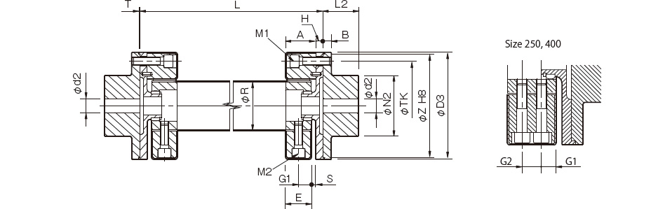
| Model | d2 | D3 | N2 | L2 | ONE | B | H | R | AND | T | G1 | G2 | S | TK | WITH | M1 | M2 | ||
|---|---|---|---|---|---|---|---|---|---|---|---|---|---|---|---|---|---|---|---|
| pilot drill hole | Minimum. | Max. | |||||||||||||||||
| CF-A-001-OZ-1360 | 8 | 9 | 22 | 56 | 36 | 24 | 24 | 7 | 5 | 30 | 22 | 1,5 | 11 | - | 2 | 44 | 52 | 2-M6 | 2-M6 |
| CF-A-002-OZ-1360 | 9 | 10 | 30 | 85 | 45 | 28 | 24 | 8 | 5 | 40 | 20 | 1,5 | 10 | - | 4 | 68 | 80 | 2-M8 | 2-M8 |
| CF-A-004-OZ-1360 | 11 | 12 | 36 | 100 | 55 | 30 | 28 | 8 | 5 | 45 | 24 | 1,5 | 12 | - | 4 | 80 | 95 | 3-M8 | 3-M8 |
| CF-A-008-OZ-1360 | 15 | 16 | 46 | 120 | 70 | 42 | 32 | 10 | 10 | 60 | 28 | 1,5 | 14 | - | 4 | 100 | 115 | 3-M10 | 3-M10 |
| CF-A-012-OZ-1360 | 15 | 16 | 46 | 120 | 70 | 42 | 32 | 10 | 10 | 60 | 28 | 1,5 | 14 | - | 4 | 100 | 115 | 4-M10 | 4-M10 |
| CF-A-016-OZ-1360 | 19 | 20 | 56 | 150 | 85 | 50 | 42 | 12 | 10 | 70 | 36 | 1,5 | 18 | - | 6 | 125 | 145 | 3-M12 | 3-M12 |
| CF-A-022-OZ-1360 | 19 | 20 | 56 | 150 | 85 | 50 | 42 | 12 | 10 | 70 | 36 | 1,5 | 18 | - | 6 | 125 | 145 | 4-M12 | 4-M12 |
| CF-A-025-OZ-1360 | 19 | 20 | 65 | 170 | 100 | 56 | 46 | 14 | 10 | 85 | 40 | 1,5 | 20 | - | 6 | 140 | 165 | 3-M14 | 3-M14 |
| CF-A-028-OZ-1360 | 19 | 20 | 65 | 170 | 100 | 56 | 46 | 14 | 10 | 85 | 40 | 1,5 | 20 | - | 6 | 140 | 165 | 4-M14 | 4-M14 |
| CF-A-030-OZ-1360 | 28 | 30 | 80 | 200 | 120 | 66 | 58 | 16 | 10 | 100 | 50 | 1,5 | 25 | - | 8 | 165 | 195 | 3-M16 | 3-M16 |
| CF-A-050-OZ-1360 | 28 | 30 | 80 | 200 | 120 | 66 | 58 | 16 | 10 | 100 | 50 | 1,5 | 25 | - | 8 | 165 | 195 | 4-M16 | 4-M16 |
| CF-A-080-OZ-1360 | 28 | 30 | 80 | 200 | 120 | 66 | 65 | 16 | 10 | 100 | 61 | 1,5 | 30,5 | - | 4 | 165 | 195 | 4-M16 | 4-M16 |
| CF-A-090-OZ-1360 | 30 | 32 | 95 | 260 | 140 | 80 | 70 | 19 | 10 | 125 | 62 | 2 | 31 | - | 8 | 215 | 250 | 3-M20 | 3-M20 |
| CF-A-140-OZ-1360 | 30 | 32 | 95 | 260 | 140 | 80 | 70 | 19 | 10 | 125 | 62 | 2 | 31 | - | 8 | 215 | 250 | 4-M20 | 4-M20 |
| CF-A-200-OZ-1360 | 35 | 38 | 110 | 300 | 160 | 90 | 80 | 19 | 15 | 145 | 72 | 2 | 36 | - | 8 | 250 | 290 | 4-M20 | 4-M20 |
| CF-A-250-OZ-1360 | 40 | 42 | 120 | 340 | 180 | 100 | 85 | 19 | 15 | 160 | 77 | 2,5 | 22,5 | 32 | 8 | 280 | 330 | 4-M20 | 8-M20 |
| CF-A-400-OZ-1360 | 40 | 42 | 130 | 370 | 200 | 125 | 105 | 29 | 15 | 170 | 95 | 2 | 28,5 | 38 | 10 | 300 | 360 | 4-M24 | 8-M20 |
* Pilot holes must be drilled into the part. The minimum value for d2 is calculated from the minimum bore diameter value in the MIKI PULLEY standard hole drilling standard and the maximum value from the maximum allowable bore diameter.
*The nominal diameter of M1/M2 bolts is equal to the quantity minus the nominal diameter of the screw thread, where the quantity is for one side.
*See floating length chart for size L. Size L must have at least enough space to accommodate M1 bolts.
[Standard hole drilling standards]
| Models comply with the old JIS standard (type 2) JIS B 1301 1959 |
The models comply with the new JIS standard (H9) JIS B 1301 1996 |
Model conforms to JIS C 4210 2001 engine standard |
||||||||||||
|---|---|---|---|---|---|---|---|---|---|---|---|---|---|---|
| Nominal hole diameter | Bore diameter (d1, d2) | Keyway width (W1, W2) | Keyway height (T1, T2) | Set screw hole (M) | Nominal hole diameter | Bore diameter (d1, d2) | Keyway width (W1, W2) | Keyway height (T1, T2) | Set screw hole (M) | Nominal hole diameter | Bore diameter (d1, d2) | Keyway width (W1, W2) | Keyway height (T1, T2) | Set screw hole (M) |
| Tolerance H7, H8 |
Tolerance E9 |
- | Tolerance H7 |
Tolerance H9 |
- | Tolerance G7, F7 |
Tolerance H9 |
- | ||||||
| 9 | 9 +0,022 0 | - | - | 2-M4 | - | - | - | - | - | - | - | - | - | - |
| 10 | 10 +0,022 0 | - | - | 2-M4 | - | - | - | - | - | - | - | - | - | - |
| 11 | 11 +0,018 0 | - | - | 2-M4 | - | - | - | - | - | - | - | - | - | - |
| 12 | 12 +0,018 0 | 4 +0,050 +0,020 | 13,5 +0,3 0 | 2-M4 | 12H | 12 +0,018 0 | 4 +0,030 0 | 13,8 +0,3 0 | 2-M4 | - | - | - | - | - |
| 14 | 14 +0,018 0 | 5 +0,050 +0,020 | 16,0 +0,3 0 | 2-M4 | 14H | 14 +0,018 0 | 5 +0,030 0 | 16,3 +0,3 0 | 2-M4 | 14N | 14 +0,024 +0,006 | 5 +0,030 0 | 16,3 +0,3 0 | 2-M4 |
| 15 | 15 +0,018 0 | 5 +0,050 +0,020 | 17,0 +0,3 0 | 2-M4 | 15H | 15 +0,018 0 | 5 +0,030 0 | 17,3 +0,3 0 | 2-M4 | - | - | - | - | - |
| 16 | 16 +0,018 0 | 5 +0,050 +0,020 | 18,0 +0,3 0 | 2-M4 | 16H | 16 +0,018 0 | 5 +0,030 0 | 18,3 +0,3 0 | 2-M4 | - | - | - | - | - |
| 17 | 17 +0,018 0 | 5 +0,050 +0,020 | 19,0 +0,3 0 | 2-M4 | 17H | 17 +0,018 0 | 5 +0,030 0 | 19,3 +0,3 0 | 2-M4 | - | - | - | - | - |
| 18 | 18 +0,018 0 | 5 +0,050 +0,020 | 20,0 +0,3 0 | 2-M4 | 18H | 18 +0,018 0 | 6 +0,030 0 | 20,8 +0,3 0 | 2-M5 | - | - | - | - | - |
| 19 | 19 +0,021 0 | 5 +0,050 +0,020 | 21,0 +0,3 0 | 2-M4 | 19H | 19 +0,021 0 | 6 +0,030 0 | 21,8 +0,3 0 | 2-M5 | 19N | 19 +0,028 +0,007 | 6 +0,030 0 | 21,8 +0,3 0 | 2-M5 |
| 20 | 20 +0,021 0 | 5 +0,050 +0,020 | 22,0 +0,3 0 | 2-M4 | 20H | 20 +0,021 0 | 6 +0,030 0 | 22,8 +0,3 0 | 2-M5 | - | - | - | - | - |
| 22 | 22 +0,021 0 | 7 +0,061 +0,025 | 25,0 +0,3 0 | 2-M6 | 10 p.m | 22 +0,021 0 | 6 +0,030 0 | 24,8 +0,3 0 | 2-M5 | - | - | - | - | - |
| 24 | 24 +0,021 0 | 7 +0,061 +0,025 | 27,0 +0,3 0 | 2-M6 | 24H | 24 +0,021 0 | 8 +0,036 0 | 27,3 +0,3 0 | 2-M6 | 24N | 24 +0,028 +0,007 | 8 +0,036 0 | 27,3 +0,3 0 | 2-M6 |
| 25 | 25 +0,021 0 | 7 +0,061 +0,025 | 28,0 +0,3 0 | 2-M6 | 25H | 25 +0,021 0 | 8 +0,036 0 | 28,3 +0,3 0 | 2-M6 | - | - | - | - | - |
| 28 | 28 +0,021 0 | 7 +0,061 +0,025 | 31,0 +0,3 0 | 2-M6 | 28 hours | 28 +0,021 0 | 8 +0,036 0 | 31,3 +0,3 0 | 2-M6 | 28N | 28 +0,028 +0,007 | 8 +0,036 0 | 31,3 +0,3 0 | 2-M6 |
| 30 | 30 +0,021 0 | 7 +0,061 +0,025 | 33,0 +0,3 0 | 2-M6 | 30 hours | 30 +0,021 0 | 8 +0,036 0 | 33,3 +0,3 0 | 2-M6 | - | - | - | - | - |
| 32 | 32 +0,025 0 | 10 +0,061 +0,025 | 35,5 +0,3 0 | 2-M8 | 32H | 32 +0,025 0 | 10 +0,036 0 | 35,3 +0,3 0 | 2-M8 | - | - | - | - | - |
| 35 | 35 +0,025 0 | 10 +0,061 +0,025 | 38,5 +0,3 0 | 2-M8 | 35H | 35 +0,025 0 | 10 +0,036 0 | 38,3 +0,3 0 | 2-M8 | - | - | - | - | - |
| 38 | 38 +0,025 0 | 10 +0,061 +0,025 | 41,5 +0,3 0 | 2-M8 | 38H | 38 +0,025 0 | 10 +0,036 0 | 41,3 +0,3 0 | 2-M8 | 38N | 38 +0,050 +0,025 | 10 +0,036 0 | 41,3 +0,3 0 | 2-M8 |
| 40 | 40 +0,025 0 | 10 +0,061 +0,025 | 43,5 +0,3 0 | 2-M8 | 40H | 40 +0,025 0 | 12 +0,043 0 | 43,3 +0,3 0 | 2-M8 | - | - | - | - | - |
| 42 | 42 +0,025 0 | 12 +0,075 +0,032 | 45,5 +0,3 0 | 2-M8 | 42H | 42 +0,025 0 | 12 +0,043 0 | 45,3 +0,3 0 | 2-M8 | 42N | 42 +0,050 +0,025 | 12 +0,043 0 | 45,3 +0,3 0 | 2-M8 |
| 45 | 45 +0,025 0 | 12 +0,075 +0,032 | 48,5 +0,3 0 | 2-M8 | 45H | 45 +0,0250 | 14 +0,0430 | 48,8 +0,30 | 2-M10 | - | - | - | - | - |
| 48 | 48 +0,0250 | 12 +0,075+0,032 | 51,5 +0,3 0 | 2-M8 | 48H | 48 +0,0250 | 14 +0,0430 | 51,8 +0,30 | 2-M10 | 48N | 48 +0,050+0,025 | 14 +0,0430 | 51,8 +0,30 | 2-M10 |
| 50 | 50 +0,0250 | 12 +0,075 +0,032 | 53,5 +0,3 0 | 2-M8 | 50H | 50 +0,025 0 | 14 +0,043 0 | 53,8 +0,3 0 | 2-M10 | - | - | - | - | - |
| 55 | 55 +0,030 0 | 15 +0,075 +0,032 | 60,0 +0,3 0 | 2-M10 | 55H | 55 +0,030 0 | 16 +0,043 0 | 59,3 +0,3 0 | 2-M10 | 55N | 55 +0,060 +0,030 | 16 +0,043 0 | 59,3 +0,3 0 | 2-M10 |
| 56 | 56 +0,030 0 | 15 +0,075 +0,032 | 61,0 +0,3 0 | 2-M10 | 56H | 56 +0,030 0 | 16 +0,043 0 | 60,3 +0,3 0 | 2-M10 | - | - | - | - | - |
| 60 | 60 +0,030 0 | 15 +0,075 +0,032 | 65,0 +0,3 0 | 2-M10 | 60H | 60 +0,030 0 | 18 +0,043 0 | 64,4 +0,3 0 | 2-M10 | 60N | 60 +0,060 +0,030 | 18 +0,043 0 | 64,4 +0,3 0 | 2-M10 |
| 63 | 63 +0,030 0 | 18 +0,075 +0,032 | 69,0 +0,3 0 | 2-M10 | 18H | 63 +0,030 0 | 18 +0,043 0 | 67,4 +0,3 0 | 2-M10 | - | - | - | - | - |
| 65 | 65 +0,030 0 | 18 +0,075 +0,032 | 71,0 +0,3 0 | 2-M10 | 65H | 65 +0,030 0 | 18 +0,043 0 | 69,4 +0,3 0 | 2-M10 | 65N | 65 +0,060 +0,030 | 18 +0,043 0 | 69,4 +0,3 0 | 2-M10 |
*All standards starting from ø11 are the same as those in the old JIS standards column.
*The positions of the set screw and keyway are not on the same plane.
*Screw set is included in the product.
*Positioning accuracy for keyway milling is determined by eye.
*Contact Miki Pulley when keyway positioning accuracy is required for a specific flange shaft.
*Refer to the technical documentation at the end of this volume for standard dimensions for bore drilling in addition to those given here.
*We can also machine shaft lines. Please contact Miki Pulley.
[Set Screw Position (Cylinder Shaft)]
Cylindrical center joint dimensions |
Distance from edge[mm] |
|---|---|
| 001 | 6 |
| 002・004 | 6 |
| 008・012 | 7 |
| 016・022・025・028 | 10 |
| 030・050・080 | 11 |
| 090・140 | 13 |
| 200・250・400 | 13 |
[Set Screw Position (Flange Shaft)]
| Flange center joint dimensions | Distance from edge[mm] |
|---|---|
| 001 | 6 |
| 002・004 | 7 |
| 008・012 | 9 |
| 016・022・025・028 | 10 |
| 030・050・080 | 15 |
| 090・140 | 15 |
| 200・250・400 | 16 |
See more technical documents here
See more technical products here
Link FaceBook Jon&Jul VietNam
-------------Communications Phone number: 0348097237 Email: Tu@jon-jul.com Address: No. 4, Street 14, Highway 13, Van Phuc Urban Area, Hiep Binh Phuoc Ward, Thu Duc City, Ho Chi Minh City, Vietnam.